


70%
60%
50%
30%
10%
40%
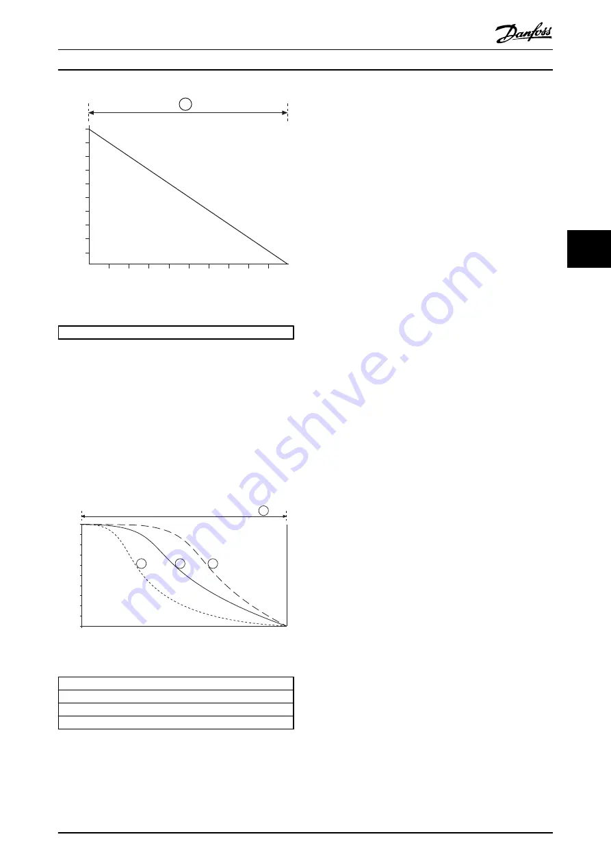
Time
V
olt
a
g
e
(%
full
volt
a
g
e)
20%
80%
90%
100%
177HA509.10
1
Illustration 5.6
1:
1-11 Stop Time
Table 5.4
5.4.3 AAC Adaptive Acceleration Control
To use AAC Adaptive Acceleration Control to control
stopping performance:
1.
Select Adaptive Control in
1-10 Stop Mode
.
2.
Set
1-11 Stop Time
.
3.
Select the required profile in
1-14 Adaptive Stop
Profile
.
0
10%
20%
30%
40%
50%
Time
S
p
ee
d
60%
70%
80%
90%
100%
17
7
H
A
51
0
.1
0
1
2
4
3
Illustration 5.7
1. Early deceleration
2. Constant deceleration
3. Late deceleration
4.
1-10 Stop Time
Table 5.5 1-14 AAC Adaptive Stop Profile
NOTE
Adaptive control does not actively slow the motor down
and will not stop the motor faster than a coast to stop. To
shorten the stopping time of high inertia loads, use brake.
The first AAC Adaptive Deceleration Control stop will be a
normal soft stop. This allows the MCD 500 to learn the
characteristics of the connected motor. This motor data is
used by the MCD 500 during subsequent Adaptive Control
stops.
NOTE
Adaptive Control will control the load according to the
programmed profile. Stopping current will vary according
to the selected deceleration profile and stop time.
If replacing a motor connected to an MCD 500
programmed for AAC Adaptive Control starting or
stopping, or if the starter has been tested on a different
motor prior to actual installation, the starter will need to
learn the characteristics of the new motor. The MCD 500
will automatically re-learn the motor's characteristics if
1-1
Motor Full Load Current
or
1-12 Adaptive Control Gain
is
changed.
5.4.4 Brake
Brake reduces the time the motor requires to stop.
During braking an increased noise level from the motor
may be audible. This is a normal part of motor braking.
CAUTION
If the brake torque is set too high, the motor will stop
before the end of the brake time and the motor will suffer
unnecessary heating which could result in damage. Careful
configuration is required to ensure safe operation of the
starter and motor.
CAUTION
A high brake torque setting can result in peak currents up
to motor DOL being drawn while the motor is stopping.
Ensure protection fuses installed in the motor branch
circuit are selected appropriately.
NOTE
Brake operation causes the motor to heat faster than the
rate calculated by the motor thermal model. If you are
using brake, install a motor thermistor or allow sufficient
restart delay (
2-11 Restart Delay
).
When brake is selected, the MCD 500 uses DC injection to
slow the motor.
Application Examples
MCD 500 Operating Instruction
MG17K402 - VLT
®
is a registered Danfoss trademark
33
5
5