Vision Phoenix 1212 S5 User Manual
110
© 2018 Vision Engraving & Routing Systems
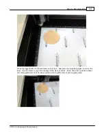
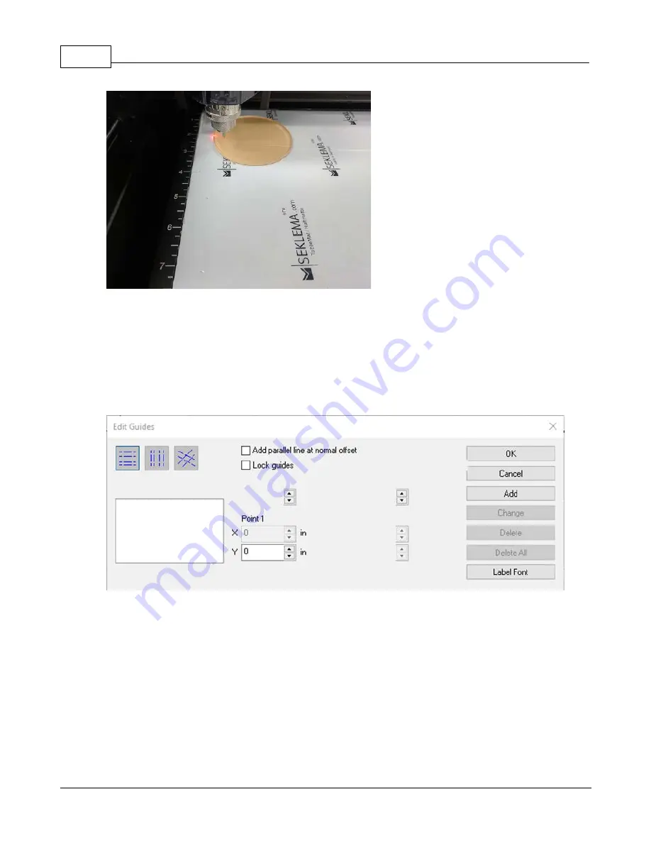
Now Jog to the left most edge of the piece of acrylic. Write down the X position. Repeat moving the
spindle to the right and bottom and write down the X/Y positions. (For rectangle objects , you can use
the X and Y readouts for the upper left and the lower right corners of your engraving area.
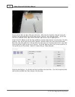
In the Vision 10 software we will now draw guidelines using the measurements we wrote down. To add a
guideline, click with the right mouse button anywhere within the plate area. Now select Edit Guides.
Select the horizontal guide icon in the top left corner and enter your Y measurement in the Y entry field.
Click add and then enter your second Y location. Press add again and then click on the vertical icon in
the top left corner of the window. Add both X values that you measured earlier.
Click Ok when finished. You should now have 4 guidelines as shown here. (Your items engraving area
and locations will differ from those shown in this example)
Summary of Contents for Phoenix 1212 S5
Page 1: ... 2018 Vision Engraving Routing Systems Vision Phoenix 1212 S5 User Manual Revised 12 7 2018 ...
Page 16: ...Vision Phoenix 1212 S5 User Manual 16 2018 Vision Engraving Routing Systems ...
Page 44: ...Vision Phoenix 1212 S5 User Manual 44 2018 Vision Engraving Routing Systems ...
Page 113: ...Step by Step Operation 113 2018 Vision Engraving Routing Systems ...
Page 121: ...Step by Step Operation 121 2018 Vision Engraving Routing Systems ...
Page 123: ...Step by Step Operation 123 2018 Vision Engraving Routing Systems ...
Page 147: ...Optional Accessories 147 2018 Vision Engraving Routing Systems ...
Page 148: ......

