background image

22

3. 

Tap 

Store

 on the touch screen and touch a position on the grid to store the shot.

4. 

Type a name for the shot into the 

Shot name*

 field and tap 

Enter

. The shot will be saved with 

the default fade time** and its thumbnail displayed on the grid.

5. 

Repeat steps 2–5 for each required shot.

Managing Shots

The Edit menu provides options that let you:

•  Rename or delete shots

•  Modify the shot fade time

• 

Swap shot positions on the grid

From the workspace tap to select 

Edit

 to reveal the edit menu.

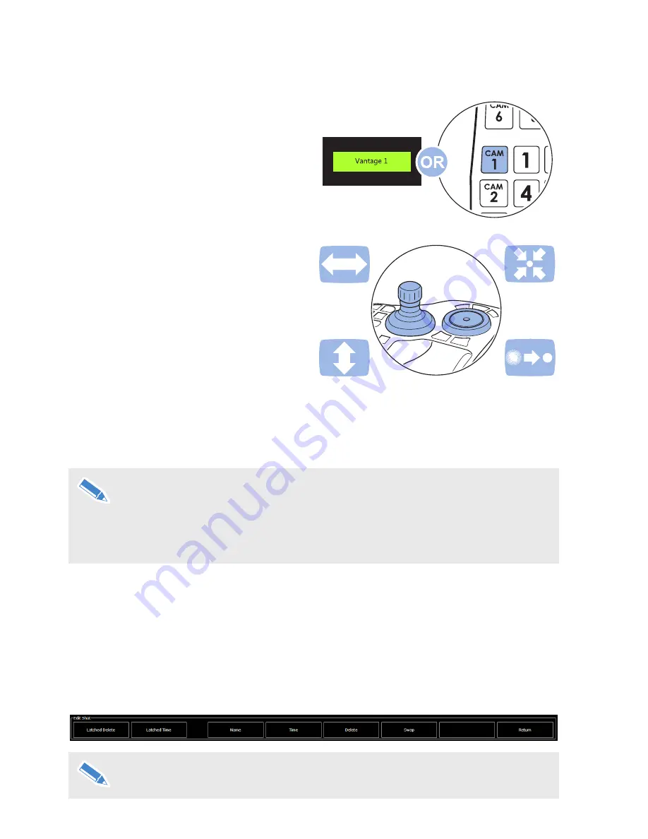
Only the latched delete, latched time and return buttons are available from the edit 

menu until you select a shot on the grid.

Adding Shots to a Show

Make sure that the required show is loaded.

1. 

Select the required camera on the touch-

screen or the control panel.

2. 

Use the joystick and controls to move the 

camera into position for the shot, and then 

frame and focus the shot.

*A shot name cannot be entered if 

Require Shot Name

 is turned off in the User 

Preferences screen. A number will be assigned to the shot instead.

**A specific fade time for the shot can be entered if 

Require Shot Time

 is turned on 

in the User Preferences screen.

For more information, see 

Shot Options

 on page 28.

Summary of Contents for mVRC

Page 1: ...User Guide Part No V4063 0010 EN www vinten com Robotic Control System...

Page 2: ...uch revision or changes Changes will be incorporated in new versions of the publication We are making every effort to ensure that our publications are updated on a regular basis to reflect changes to...

Page 3: ...d Connections 5 Joystick Panel Controls and Connections 6 Upgrade Options 7 Connecting the VRC 8 Starting the VRC 9 Adding Robotic Camera Units to the System 10 Using the Joystick Panel 12 Using the T...

Page 4: ...check cables for signs of damage Damaged cables can cause personal injury and or damage the equipment It is the responsibility of the local organisation to ensure that the product is periodically chec...

Page 5: ...ent it is recommended that only trained personnel be allowed to work in the active areas where remote controlled robotic equipment is located The safe operating zone is a minimum of 1 m 3 ft Safety No...

Page 6: ...4 2 Getting Started Box Contents 1 VRC computer 2 Joystick panel 3 VRC power supply NI USB connecting cable NI Power cable x3 NI User guide 1 2 3 NI Not Illustrated...

Page 7: ...s 1 Touch screen interface 2 Adjustable stand 3 Power button 4 Power socket 5 Network port 6 USB3 ports 7 VESA mounting holes X4 8 USB 2 ports 4 1 3 2 5 6 6 7 For more information on the VESA mount se...

Page 8: ...6 Joystick Panel Controls and Connections 1 Main joystick control 2 Shot control keys 3 Focus controls 4 Keys not currently used 5 Hand rest pad 6 Camera selection keys 7 USB port 1 2 3 4 5 6 7...

Page 9: ...d VRC Total Control V4063 8002 Any number of Vantage heads can be controlled PTZ Control V4063 8003 Control a single PTZ camera Sony or Panasonic ICE Fusion V4063 8004 Adds control of Vinten ICE and F...

Page 10: ...with the supplied USB lead The VRC computer connections are located on the rear of the product See the section VRC Computer Components and Connections on page 5 For more information on connecting up r...

Page 11: ...the rear edge of the case Starting the VRC Application When the VRC computer has booted up double tap on the Fusion Client icon If only one user name is set up on the system with no password set the V...

Page 12: ...chased they should be applied to the VRC system during set up For more information see About Screen and License Management on page 34 If you are unfamiliar with the VRC interface see Using the VRC on...

Page 13: ...ly Changes button 6 Tap the OK button to allow the software to restart When the VRC restarts added cameras are available for selection from the Camera selection and Status Bar Cameras and components c...

Page 14: ...enables you to select and control connected robotic cameras Additional keys are available to select cameras and other useful functions Using the VRC Joystick Camera Controls The joystick panel provid...

Page 15: ...cess to functions when the operator is using the joystick to control cameras 1 Camera shot control keys fade stop cut 2 Function keys not currently used 3 Numeric keypad not currently used 4 Camera se...

Page 16: ...the current show or the shots stored for the currently selected camera depending on the setting of the Per Camera configuration option 2 Camera selection and Status Bar The robotic cameras can be sel...

Page 17: ...show file F Grey Indicates shots that are available for selection A B C D E Camera Selection Status Bar Available robotic cameras can be selected from this bar The colour of the camera button indicat...

Page 18: ...shot to the selected shot in the time duration stored in the shot This function can be latched to immediately fade to a shot when it is selected Store Stores the shot on the currently selected camera...

Page 19: ...on page 34 Exit Exits the VRC application Return Closes the menu Edit menu Tap Edit to display the Edit menu This has options that let you rename shots modify the fade time delete shots re save a shot...

Page 20: ...the adjusted focus Keep Shot After the focus has been adjusted tap Keep Shot to return the camera to the shot s original pan tilt and zoom settings keep the adjusted focus setting and store the adjus...

Page 21: ...botic cameras Turn X4 mode on and off Enter the CCU control screens Enter the Device Configuration screen X4 The default zoom mode zoom proportional ensures that the speed of the pan and tilt movement...

Page 22: ...amera control systems originally being used purely for the creation of TV shows The term has been retained for consistence with existing users Show management A show is a collection of stored shots fr...

Page 23: ...complete the import Exporting a show 1 Tap to select the desired show from the grid to export 2 Tap the Export button 3 Use the file browser to place the show in the desired location Tap Save to compl...

Page 24: ...enu Only the latched delete latched time and return buttons are available from the edit menu until you select a shot on the grid Adding Shots to a Show Make sure that the required show is loaded 1 Sel...

Page 25: ...y its time 4 Repeat until all of the desired shots have been modified 5 Tap Latched Time again to exit this mode Other Edit Options Edit Menu Option Description Name Tap on the shot in the grid you wi...

Page 26: ...sting Shot Fade Times The stored fade time can always be modified on air in real time using the time slider on the virtual joystick The maximum fade time is 120 seconds Latched Cut or Fade Function Th...

Page 27: ...ore it is on air the VRC operator will want to take control at the joystick panel and check the framing and focus of the shot and trim the shot as needed This lets the operator correct for things like...

Page 28: ...iguration groups Grid Display Options Panel Options Shot Options Camera Control Shot Preferences Group Display Preferences CCU Recall Preferences Grid Display Options Options Description Grid Size Tap...

Page 29: ...stest speed of movement The Deadband setting is used to adjust the amount of play that is felt in the joystick before the camera or lens starts to move Before changing the Gain or Deadband settings fo...

Page 30: ...tions ON Blue OFF Black Deselect A camera that has been selected can be deselected by tapping it on the screen A camera can only be deselected by selecting a different camera Always Take Rudely Select...

Page 31: ...fferent camera automatically deselects the first shot Allows you to select shots on multiple cameras and then cut or fade to all of the shots at the same time Delete Warning Every time you delete or r...

Page 32: ...he Primary Panel Groups and Preview Panel Groups bars if enabled above the Stored Shot Editing grid Displays the Primary and Preview Panel Groups bars between the Stored Shot Editing grid and the Came...

Page 33: ...Superuser has the right to add and delete other users At least one Superuser must be present on the system to allow access to User Management The last remaining Superuser cannot be removed Adding a U...

Page 34: ...mber the preview monitor is connected to on the switcher 4 Change the switcher number level using the arrows in the Level field 1 2 3 Refer to the documentation supplied with the video switcher 4 Conf...

Page 35: ...ras quickly during operation 1 To access the screen tap Menu Sort Cameras 2 Tap and drag a camera to a new location example shows camera named PTZ4 being moved to the first position 3 Continue to repo...

Page 36: ...itional features and functions are purchased to upgrade the VRC a license key is issued This license key must be applied to activate the new features When you buy a software license you will be issued...

Page 37: ...lso be inverted to reverse joystick control Axis gain settings can be easily set changed or cleared 1 2 3 Adjust the gain settings for Pan or Tilt tapping the up down arrows Tapping the Default button...

Page 38: ...roduction and tilt set with the camera platform horizontal 1 Drive the camera to the desired position on the axis 2 Tap the Zero button in the appropriate axis panel 3 The current position marker blue...

Page 39: ...t any time The procedure described below is identical for all axes and positive and negative limits 1 Tap the Clear button for the appropriate axis limit point positive or negative to remove the curre...

Page 40: ...has been chosen to provide an example For a full list of functions and controls for each camera protocol see CCU Database on page 41 Camera Functions Tab The first tab on the CCU screen displays the...

Page 41: ...een On many cameras it is possible to access and control the built in menu system Changes can be made and stored remotely It is important that the user can see the on screen display of the camera via...

Page 42: ...screen display or video output Some functions have an indicator bar and display the setting value for precise adjustments Grey Up Down arrows indicate a setting cannot currently be adjusted This coul...

Page 43: ...tween cameras they are operated in the same way as demonstrated in the section Typical Camera Functions and CCU Controls on page 38 Sony CNA 1 Features Iris Mode Green Gain Nd Filter Blue Gain Cc Filt...

Page 44: ...Pedestal Master Black Shutter Select Iris Synchro Scan Menu Navigation ISO Gain Hitachi Broadcast Cameras Features Color Bars Blue Gain Iris Closed Blue Ped AWB Green Ped ABB M Ped Master Black Red G...

Page 45: ...ain Auto Iris Knee Point Auto Knee White Balance B On Screen Overlay Master Black B Shutter Select Black Gamma WB Mode Shutter Speed Menu Knee Slope AGC White Balance R Custom Picture Master Black R R...

Page 46: ...21 2 in Width 83 mm 3 3 in Touch screen Display Panel Specification 21 5inch TFT LCD LED Backlight 16 9 1920 x 1080 FHD Illumination 250nits Viewing Angle 170 Horizontal 160 Vertical Physical Data He...

Page 47: ......

Page 48: ...Publication No V4063 4980 1 www vinten com Vinten A Vitec Group brand...

Reviews: