background image

13

Operation and maintenance, Discfilter HPF2200-series PFLC

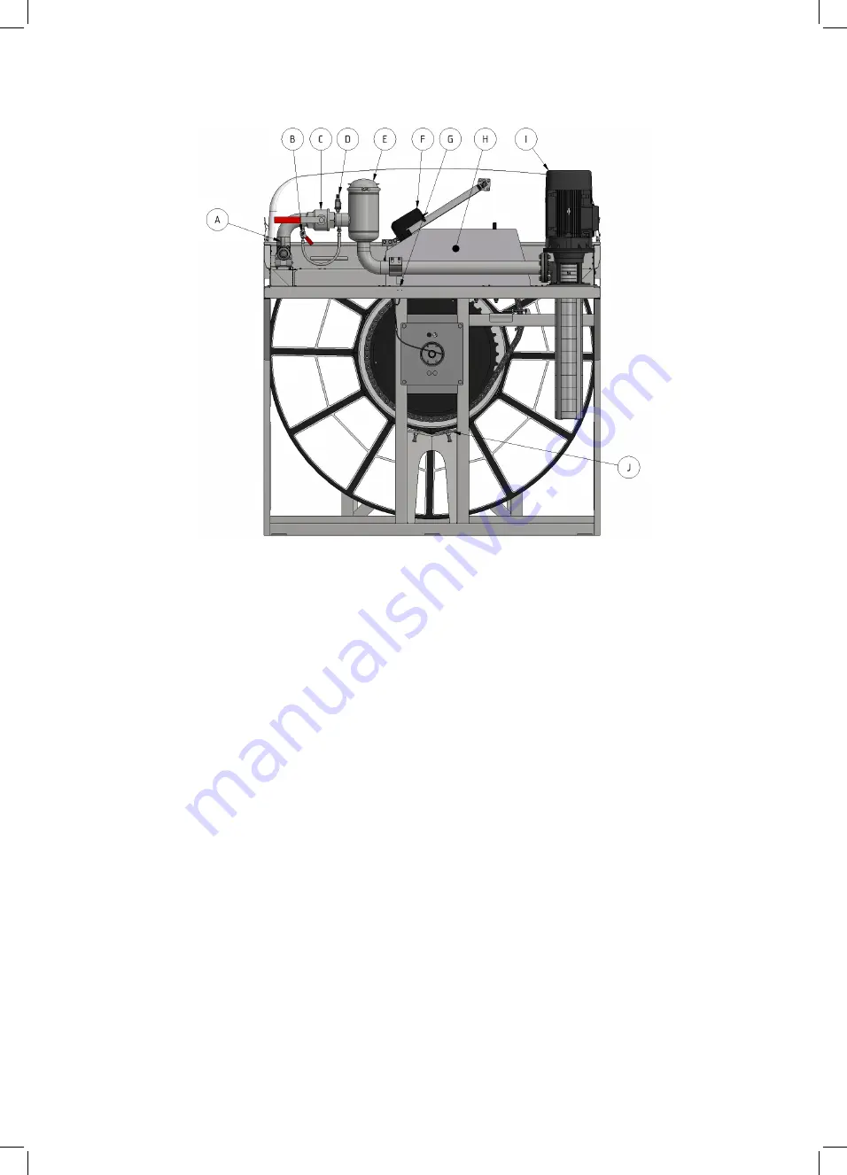
Figure 3.7 Hydrotech Discfilter in HPF2200 series type 2 (outlet side). 

A. Manometer 

B. Bypass valve for nozzle check 

C. Shut off valve for nozzle check 

D. Pressure transmittor - dry running protection for pump 

E. Strainer 

F. Linear actuator for opening filter cover 

G. Lubrication point 

H. Drive motor 

I. Backwash pump 

J. Drum lifter

Summary of Contents for Hydrotech Discfilter HPF2200 Series

Page 1: ...Discfilter HPF2200 series PFLC Operation and maintenance manual Revision 2020 08 26...

Page 2: ...fety 7 2 7 Safety instructions 8 3 HYDROTECH DISCFILTER HPF2200 SERIES 9 3 1 Reception 9 3 2 Storage 9 3 3 Overview 10 3 3 1 HPF2200 type 1 filter with tank 10 3 3 2 HPF2200 type 2 filter without tank...

Page 3: ...el control 21 5 2 3 Operating mode REMOTE Remote control 21 5 2 4 Service mode HAND 22 5 3 Backwash system 22 6 FUNCTION 23 6 1 Intended use 23 6 2 Non intended use 23 6 3 Filtration and backwash proc...

Page 4: ...tensioner to achieve correct tension 36 7 5 3 Replacing the drive chain 38 7 6 Drive unit 38 7 7 Inlet gasket 38 7 7 1 Checking the inlet gasket 38 7 7 2 Replacing the inlet gasket 39 7 8 Lifting the...

Page 5: ...nored it may result in serious personal injury and or damage to equipment The manual must always be available to the personnel working with the equipment It is important that The manual and other rele...

Page 6: ...s to be pressurised Before carrying out maintenance work the main power switch see Figure 2 3 must be turned to the OFF 0 position and locked with a padlock Maintenance and service may only be perform...

Page 7: ...and maintenance personnel may only handle those parts of the equipment they have been trained for The operator may need to work inside the safety barrier and in the safety zone during maintenance and...

Page 8: ...perfor ming any work on the filter Access to the filter by unauthorised persons is strictly prohibited Outdoor installations must be fenced in The drum can start rotating without warning if automatic...

Page 9: ...ing the equipment 3 2 Storage Some precautions must be taken to prevent damage to equipment if a long storage time is ne cessary several weeks or more The equipment should preferably be stored indoors...

Page 10: ...areshown Figure 3 1 Hydrotech Discfilter in HPF2200 series type 1 side view A Inlet side B Filter cover C Drive side Figure 3 2 Hydrotech Discfilter in HPF2200 series type 1 inlet side A Linnear actua...

Page 11: ...200 series type 1 outlet side A Drain valve B Bypass valve for nozzle check C Manometer D Lubrication point E Shut off valve for backwash pipe F Pressure transmittor dry running protection for pump G...

Page 12: ...w A Inlet side B Inlet passage C Filter cover D Outlet side Figure 3 6 Hydrotech Discfilter in HPF2200 series type 2 inlet side A Mounts for level transmittors B Linear actuator for opening cover C Li...

Page 13: ...r in HPF2200 series type 2 outlet side A Manometer B Bypass valve for nozzle check C Shut off valve for nozzle check D Pressure transmittor dry running protection for pump E Strainer F Linear actuator...

Page 14: ...g the filter Filter type serial number and year of manufacture are stated on the marking plate The filter type and serial number are also stated on the front of this manual 3 4 1 Definition of filter...

Page 15: ...d when lifting filters in wooden crates Filters with a tank can be lifted using a crane or overhead crane by using the filter s lifting lugs or with a forklift truck WARNING The work area must be fenc...

Page 16: ...scfilter HPF2200 series PFLC Filters without a tank can be lifted using a crane or overhead crane by using the filter s lifting lugs or by the use of a forklift Figure 4 2 Shows how lifting devices ar...

Page 17: ...ons The filter must be installed on a flat surface that offers sufficient load bearing capacity The filter is to be bolted to the foundation The filter must be level in both directions see Figure 4 4...

Page 18: ...is very important to prevent galvanic corrosion Ideally use a ca ble with a cross section of 10 16 mm2 The cable should be connected to the same electrical potential as the drive system 4 5 Checking d...

Page 19: ...e in water level between the inside and outside of the filter drum than 450 mm will damage the filter 6 When the water level inside the filter tank chamber exceeds the suction pipe of the pump or the...

Page 20: ...s standard depending on region of delivery If the filter is equipped with a Hydrotech standard control the filter has three operating modes 1 Automatic level control AUTO mode 2 Remote control REMOTE...

Page 21: ...Operating mode AUTO Automatic level control With automatic level control drum rotation and the backwash pump are activated once the le vel difference between filtered and unfiltered water exceeds an a...

Page 22: ...ress the pump Start button see Figure 5 5 The operator panel main menu also shows the water levels of unfiltered In and filtered water Out as well as the level difference between them Level Diff 5 3 B...

Page 23: ...sides of the filter segments whilst clean water passes through the filter medium to the outside of the filter segment 3 Operating mode AUTO The solid particles trapped on the inside of the filter medi...

Page 24: ...o the HAND position 2 Open the cover on the side where the backwash pipe is located 3 Extend the backwash ramp see Figure 7 2 3 Open the bypass valve see Figure 7 1 4 Close the main valve The water fl...

Page 25: ...n damage the nozzle 11 Assemble the parts in the reverse order Make sure the nozzle nut reaches the stop position when turned a turn clockwise 12 Place the backwash ramp in its original position 13 Op...

Page 26: ...h strainer 1 Turn the main power switch to the OFF 0 position and lock with a padlock 2 Loosen the wing nut and remove the clamping ring B in figure 7 5 3 Lift off the wash water filter cover A in fig...

Page 27: ...e connecting pipe for the backwash water see Figure 7 7 7 8 The swivel s lubrication points are shown in Figure 3 3 and Figure 3 6 7 3 2 Lubricating drum bearings The bearings lubrication nipples are...

Page 28: ...Drain the chamber filter tank 3 Check the drum bearings with respect to wear If the distance between the bearing housing A and the shaft B is less than 22 mm see Figure 7 8 the drum bearing must be r...

Page 29: ...leaning be comes clear if the frequency of automatic backwash starts increases Additional cleaning can be chemical cleaning or cleaning with a high pressure washer When using a high pressure washer a...

Page 30: ...in the HPF2200 series as standard are prepared with a chemical ramp to make removal of long term clogging of the filter media possible The Hydrotech chemical trolley HCT option is connected to the ch...

Page 31: ...y turning it turn anticlockwise see Figure 7 13 b 3 Clean the nozzle with compressed air or a plastic brush Never use a wire brush metal pins or similar as these can damage the nozzle 4 Refit the nozz...

Page 32: ...efit all filter panels on just ONE side of the disc see Figure 7 14 1 Turn the mode selector to HAND 2 Select Service on the operator panel see Figure 7 15 3 Select Pump Drum see Figure 7 16 Use the J...

Page 33: ...lter HPF2200 series PFLC 5 Undo the filter segment cover screw and remove the cover see Figure 7 18 6 Pull out the filter panel see Figure 7 19 Figure 7 18 The filter segment cover is removed Figure 7...

Page 34: ...lter cloth facing inwards see Figure 7 20 Incorrect installation of the filter panels can cause damage to the filter segments 8 Replace the filter segment cover and tighten the screws Maximum tighteni...

Page 35: ...nd lock with a padlock 2 Remove the motor cover to access the chain 3 Stretch the chain by turning the drum by hand in the non operational direction 4 Check the tension of the chain s return section i...

Page 36: ...and lock with a padlock 2 Remove the motor cover to access the chain 3 Remove the flooring tile with the three screws marked blue in figure 7 22 This is done by rele asing the tension of the screw and...

Page 37: ...osening the screws so that the bracket under neath the beam dont fall off Loosen the nut on the adjustment screw 5 Adjust the long screw until the chain gets the correct amount of tension 6 Secure the...

Page 38: ...again as set out in section 5 1 7 6 Drive unit NB Prior to servicing read section 2 7 For information about the drive unit see Appendix D 7 7 Inlet gasket NB Prior to servicing read section 2 7 7 7 1...

Page 39: ...ion 5 Remove the inlet gasket 6 Fit a new inlet gasket 7 Start operations again as set out in section 5 1 7 8 Lifting the drum The filter is equipped with two drumlifting devices each located at the g...

Page 40: ...ifter is operated by tightening the screw the screw marked blue in figure 7 8 2 This will push on the center of the inside ring of the drum lifting it vertically Figure 7 8 2 The drum is lifted by tig...

Page 41: ...that the drum is being held close to the centreline of the filter during the entire process 7 8 2 Lifting the drum on filters with tank The procedure for lifting the drum on a filter with tank is the...

Page 42: ...surfa ces minimise corrosion particularly in salt water applications Twice a month or another interval based on expe rience from the application in question Check the nozzles with respect to clogging...

Page 43: ...rmation about lubrication Symbol displaying moving parts Neg ligence to comply with safety regula tions may lead to injury This symbol is placed where certain attention is needed when handling the fil...

Page 44: ...ech filters or any other product used together with Hydrotech filters please visit www hydrotech se Click on Manuals technical information Locate the desired product manual and select manual by clicki...

Page 45: ...r HPF2200 series PFLC Hydrotech AB A Veolia Solutions Technologies Company Mejselgatan 6 235 32 Vellinge Sweden Telephone 46 0 40 42 95 30 Fax 46 0 40 42 95 31 E mail mailbox hydrotech se Web www hydr...

Reviews: