background image

Dynamic Host Configuration Protocol (DHCP) server, as defined by RFC 2181. This server provides the

IP addresses for both the CM and subsequent PC devices that follow

Time of Day (TOD) server, as defined by RFC 868 for the purpose of time-stamping operational system

events

Trivial File Transfer Protocol (TFTP) server, as defined by RFC 1350 for the purpose of registering and

downloading CM configuration files for individual customer service. These configurations could include

quality of service (QoS) parameters, baseline privacy (BPI) implementation, operating frequency

assignments, the number of host devices, etc.

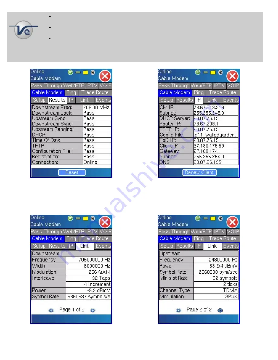
Once online, the user can go to the IP tab. This screen provides all the information related to the various IP addresses acquired or

used during the connection process.

The Link Turn Up tab provides information about the packets received, the downstream signal (frequency, modulation, level, SNR)

and about the upstream signal (frequency, level, modulation).

The Events section provides a time stamp list of events that have occurred during the connection process.

CX100/110/120/150/180 series e-Manual D07-00-002 Rev B01

Page 30 of 39

Summary of Contents for CX100 Series

Page 1: ...nto a foreign language or be transmitted electronically without prior agreement and written consent of VeEX Incorporated as governed by International copyright laws Information contained in this manua...

Page 2: ...Locations 7 0 Single Channel Measurement 8 0 Tilt Measurement 9 0 System Scan 10 0 Forward and Reverse Path Ingress 11 0 Upstream Signal Generator CX120 150 180E models only 12 0 DOCSIS Cable Modem CX...

Page 3: ...ll CX products are lightweight rugged and weather resistant instruments featuring signal level meter capabilities Certain models can be equipped with a cable modem option to validate DOCSIS 2 0 and Eu...

Page 4: ...this device agrees that it has received a license solely to use the software as embedded in the device and the purchaser is prohibited from copying reverse engineering decompiling or disassembling th...

Page 5: ...autions and requirements Go back to top 4 0 Basic Operations 4 1 Keypad The unit is powered on and off from the red key on the keyboard area In order to turn off the unit press the power key for at le...

Page 6: ...n the transparent door covering the screen Then take out the stylus available on the top door i e door protecting the connector panel Keep the LCD cover closed when using the unit on non touch screen...

Page 7: ...alysis CX180 only is also performed on this test port Note Maximum Voltage input is 100VAC 140VDC Auxiliary This connector provides access to the DOCSIS cable modem and Upstream Generator functions wh...

Page 8: ...ions include Transfer measurement results and test profiles between the instrument and a computer using ReVeal CX software Upload download channel tables between the instrument and a computer using Re...

Page 9: ...The LED is off when the Cable Modem or USG are inactive Fast flashing green indicates the Cable Modem is ready Slow flashing indicates the Cable Modem has achieved the initial down stream and up strea...

Page 10: ...standard accessory Additional tables can be created either from a blank table or from existing ones The test set and the PC software can exchange the tables for easy update Please consult the ReVeal C...

Page 11: ...nder Settings or by using ReVeal TM PC software Three locations are provided pre loaded on the unit Ground Block Set Top Box and Tap Go back to top 7 0 Single Channel Measurement The Single Channel SL...

Page 12: ...area The following measurement information is provided for analog signals Video Power Level graphic bar and numeric in dBmV Audio1 Power Level graphic bar and numeric in dBmV V A1 Ratio numeric in dB...

Page 13: ...or analog video carrier level measurements When testing a digital channel the unit first tries to achieve digital lock Once achieved the unit displays the related digital measurements as well as the c...

Page 14: ...a measure of how tightly symbols are recorded with respect to their optimum location based on the Error Vector Magnitude or EVM MER determines how much margin the system has available before a failure...

Page 15: ...BER Post Error Seconds numeric is the error rate of the signal after the FEC has corrected all the possible errors Severely Error Seconds numeric Constellation graphic Max Adjacent Channel Delta numer...

Page 16: ...and location relative to their ideal positions allows you to draw some conclusions about the nature of an impairment Graphics courtesy of Cisco and SCTE The following impairments can be assessed visu...

Page 17: ...drant Go back to top 8 0 Tilt Measurement Tilt measurement is used to check the channel levels at the lowest and highest frequencies because level variations across the frequency spectrum are indicati...

Page 18: ...ls or DOCSIS carrier levels As a rule of thumb analog carriers should be no more than 6 to 10dB higher compared to digital channels while DOCSIS channel levels should range between 10 to 10 dBmV to al...

Page 19: ...Power Level in dBmV Max Power Level in dBmV Min Delta V A1 in dB applies to analog channels only Max Delta V A1 in dB applies to analog channels only Once the test is completed or stop by the user a...

Page 20: ...via an external source Sometimes defined as a frequency selective impairment Ingress can be broadly categorized as follows Narrow band ingress The predominant coupling mechanism for ingress noise is...

Page 21: ...t the wheel icon on the left bottom part of the screen Once selected then by pressing the up or down arrow or tapping on the corresponding arrow of the wheel on the screen the attenuation y axis will...

Page 22: ...G Available on CX120 CX150 and CX180 models only The Upstream Signal Generator USG function generates a QAM signal for upstream or reverse path testing The main menu displaying the USG capability will...

Page 23: ...version or 5 to 65 MHz Euro DOCSIS version in 1MHz steps while the level is adjustable over a dynamic range of 5 to 58 dBmV in 1dBmV steps The Enhanced USG FEC option is available for the CX120 and CX...

Page 24: ...packet sync byte 0x47 The bits per symbol is the modulation s power of 2 x Forward Error Correction For example in 64 QAM modulation 64 2 6 so the bits per symbol is 6 The Forward Error Correction FE...

Page 25: ...the North American standard and vendors aggressively introduced products in compliance with this standard MSOs in turn defined upgrade and construction programs to increase the supporting bandwidth of...

Page 26: ...MD sublayer for Downstream based on ITU T Rec J 83 Annex B with either 64 or 256 quadrature amplitude modulation QAM concatenation of Reed Solomon and Trellis forward error correction FEC in addition...

Page 27: ...ialize and bring the setup screen In the setup screen first select the mode for the channel In auto the cable modem will scan all the channels available on the selected channel table In manual the use...

Page 28: ...e connection process is listed As a step is performed an in progress indicator informs the user of the current status After a step is completed a Pass or Fail status is provided If any one of the step...

Page 29: ...ontinuity between itself and all CM units in the same domain When a CM receives its first keepalive message it reverts to a fine power ranging The CM now forwards a bandwidth request to the CMTS which...

Page 30: ...include quality of service QoS parameters baseline privacy BPI implementation operating frequency assignments the number of host devices etc Once online the user can go to the IP tab This screen provi...

Page 31: ...details The Pass Through function provides the ability to emulate a real cable modem Once the cable modem is online select the pass through tab then connect the customer network LAN PC to the manageme...

Page 32: ...els and or up to 6 user programmable digital channels Each channel table has its own installation check settings The user can modify these settings with ReVeal CX and load the updated configurations t...

Page 33: ...ts are performed for each analog channel Video Power Level in dBmV Audio1 Power Level in dBmV V A1 Ratio in dB Audio2 Power Level in dBmV Video Audio2 Delta in dB C N in dB Max Adjacent Channel Delta...

Page 34: ...alog channels only Digital channels only or both During the test a status indicator is displayed as well as the current progression Once completed the yellow square is replaced by a green square if th...

Page 35: ...Go back to top 13 2 Settings Go back to top 13 3 Files Go back to top 13 4 Help CX100 110 120 150 180 series e Manual D07 00 002 Rev B01 Page 35 of 39...

Page 36: ...Go back to top 13 5 Backlight CX100 110 120 150 180 series e Manual D07 00 002 Rev B01 Page 36 of 39...

Page 37: ...Coverage VeEX Inc warrants software and firmware materials against defects in materials and workmanship During the warranty period VeEX will at its sole discretion either Repair the products Replace t...

Page 38: ...specifications for the product Improper installation by the customer Go back to top 15 0 Product Specifications CX100 110 120 150 Models Click here CX180 Model Click here Go back to top 16 0 Certific...

Page 39: ...0 About VeEX VeEX Inc the Verification EXperts is an innovative designer and manufacturer of test and measurement solutions addressing numerous technologies Global presence through a worldwide distrib...

Reviews: