Note:
The
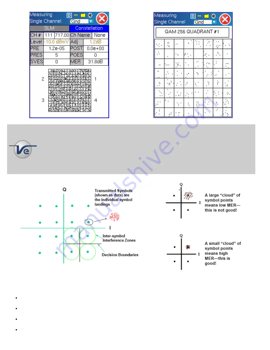
Constellation diagram
is an X/Y plot of the I (In phase axis) and Q (Quadrature axis)
components of the QAM signal and is useful for viewing impairments due to ingress and/or modulation
problems present on the digital signal. A symbol (essentially a waveform representing one or more bits)
should ideally appear as a compact or clean dot in the center of each symbol box. Decision boundaries exist
within the constellation so that if the symbol falls within the boundary, the correct data is received. If due to
noise or other interference, the symbol falls outside the boundary, the data will be in error. Error detection and
and correction (e.g. FEC) will attempt to the correct these errors thus avoiding video impairments. Observing
the symbol's shape and location relative to their ideal positions allows you to draw some conclusions about the
nature of an impairment.
Graphics courtesy of Cisco and SCTE
The following impairments can be assessed visually;
Gain compression pulls the symbol clusters into the center while the middle ones are unaffected. Gain compression can
result from poor or bad amplifiers, IF equalizers and up/down converters.
Broadband or system noise causes symbol clusters to enlarge and this increases the probability of errors. An error occurs
when the dot is pulled across a decision boundary.
Coherent interference like CSO/CTB, spurs or ingress produce symbol clusters with a hole in the center so they appear as
"donuts". This can also be a result of laser clipping or sweep interference.
Phase noise causes the symbol clusters to appear as arcs particularly those near the edges of the constellation. Phase
CX100/110/120/150/180 series e-Manual D07-00-002 Rev B01
Page 16 of 39


