background image

Page 12 


                                        3001002 Rev. P    

Section 6  

Initial assembly

Certain accessories must be installed in the Precision Flow

®

 unit before it can be used. These 

will normally be supplied in a separate package from the main unit as some are country-
specific.The power cord plugs into the IEC60320-compliant receptacle on the rear panel.

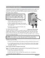
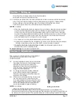
6a. Oxygen sensor installation

CAUTION

: The oxygen sensor is in a sealed 

package. Un-sealing the package admits oxygen 

to the sensor, which should be replaced after 1 

year. Do not open the package until the unit is to 

be used. Write the expiration date on the oxygen 

sensor cell.


1. Remove three (3) securing screws from the access  

   panel. 

Pull the panel away from the unit.


2. Insert the threaded end of oxygen sensor into port,  


  and screw into place. Sensor should be hand-tight only.  


  Do not use tools.


3. Plug sensor cable into connector. Replace cover.  


  Do not over-tighten screws.

6b. Inlet gas filter trap assemblies.
Gas filters and traps are supplied in a separate container with the O

2

 sensor and must be  

installed before first-time use. The filter and trap assemblies have a quick-disconnect fitting 
which connects to the main unit, and a DISS gas fitting for either an oxygen or an air hose.

Note: The quick-disconnect tubes for the oxygen and air filters are different sizes, so that they 
can not be connected incorrectly.

WARNING: 

Never attempt to run the Precision Flow

®

 unit without the inlet gas filters. 

Particles in the inlet gas flow will cause irreparable damage to the mass flow sensors.

Installing the gas inlet filters


1. Remove any protective tape from the gas inlet connectors at the back of the main unit.


2. Push the filter assembly firmly in the correct connector opening until it is fully engaged  


  and it clicks. The filter can rotate but not pull out. Filter bowls should be vertical (glass 


  side down) when in use.

Removing gas inlet filter assembly from main unit

Note

: It is not normally necessary to remove the filter and trap assemblies, but shipping and 

packing are easier if the filters are detached first.


1. Press the filter assembly into the main unit.


2. Hold the locking ring in place and push it back against the main unit backplate.


3. Pull the filter assembly straight out.

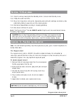
Oxygen Sensor Access Panel

Summary of Contents for precision flow

Page 1: ...Precision Flow Operating Instruction Manual...

Page 2: ...ction 2 Overview 6 Section 3 Principles of operation 7 Section 4 Controls displays connections 8 Section 5 Modes of operation 11 Section 6 Initial assembly 12 Section 7 Setting up 13 Section 8 Adjustm...

Page 3: ...n Emerging and Newly Identified Health Risks SCENIHR has evaluated the exposure to DEHP for the general population and patients during medical procedures In some cases the exposure is significant and...

Page 4: ...ion or maintenance performed by anyone not trained by Vapotherm staff or official training documentation When handling any part of the Precision Flow always follow hospital infection control guideline...

Page 5: ...ounding connection do not operate the device Medical electrical equipment needs special precautions regarding electromagnetic radiation Portable and mobile RF communications equipment can affect medic...

Page 6: ...e adjusted via a single setting control knob on the front panel All values and alarms displayed in a single large color coded panel Flow range 1 40 lpm Oxygen percentage is fully adjustable from 21 to...

Page 7: ...charged The battery is not intended for patient transport gas flow will cease Disposable patient circuit The disposable patient circuit DPC is comprised of the disposable water path DWP vapor transfer...

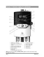
Page 8: ...ge type 4 Vapor transfer cartridge fault 5 Gas supply fault 6 Status LED 7 Run Standby button see note 8 Setting control knob 9 Alarm mute button 10 Alarm muted LED 11 General fault 12 Water out 13 Bl...

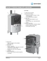
Page 9: ...LED indicates one or more alarms are muted 4 Setting control knob Press to select which variable to adjust Rotate to adjust to new value Press again to set value 5 Hinged door Opens to install or remo...

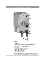
Page 10: ...nt 3 Access panel for oxygen sensor see note 4 Pole clamp 5 Power cord connection and fuse holder 6 DISS or NIST oxygen connection 7 DISS or NIST air connection 8 Gas inlet filters and traps Note Writ...

Page 11: ...scrub the ports Do not apply organic solvents or bleach Section 5 Modes of operation Mode Action Indicator light color Sleep Display in sleep mode no gas flow Amber Standby Input parameters can be ad...

Page 12: ...installed before first time use The filter and trap assemblies have a quick disconnect fitting which connects to the main unit and a DISS gas fitting for either an oxygen or an air hose Note The quic...

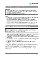
Page 13: ...t not more than 40 102cm above the floor Fixed rail supports may also be used Use with Vapotherm approved IV poles 7 4 Connect oxygen and air supply hoses to correct inlets then connect them to the wa...

Page 14: ...5 2 Fit the delivery tube to the disposable water path as shown Press firmly into place Insert fully Both latches must click shut Assembled disposable patient circuit ready for insertion Water inlet...

Page 15: ...ward as shown 7 6 3 Slide disposable patient circuit downward into the docking station until it stops 7 6 4 Press down firmly to ensure correct seating NOTE If the hinged door does not close easily ch...

Page 16: ...emperature There will also be a corresponding cartridge indicator on the lower right hand side which will identify what type of disposable patient circuit is in place Blue High or Red Low To enter Run...

Page 17: ...tube to stop the flow of water into disposable patient circuit whenever the unit is in standby mode To adjust settings See section 8 Adjustments For alarms and troubleshooting See section 12 Alarms S...

Page 18: ...down unit returns to default settings Section 9 Connecting to patient 9 1 Wait for desired set temperature to be reached before placing the cannula on the end of the patient delivery tube The flashin...

Page 19: ...s at flow rates less than 5 lpm low flow cartridge or less than 10 lpm high flow cartridge To minimize condensation it is recommended not to set the temperature higher than 34 C if using flow rates le...

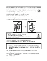
Page 20: ...es 11 8 Slide the disposable patient circuit into the docking station and close the door 11 9 Hang new sterile water on the IV pole hook 11 10 Wipe the spike on the water inlet tube with 70 90 isoprop...

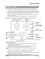
Page 21: ...E PRIORITIES MEDIUM PRIORITY alarms require immediate attention and are indicated by rapid intermittent tones fast triple beeps LOW PRIORITY alarms require attention as soon as reasonably possible and...

Page 22: ...cannula type re install DPC Water out flashing Medium Priority No water in disposable water path Gas flow continues without heat ing or water circulation Sterile water empty or obstructed inlet tube D...

Page 23: ...path cartridge delivery tube None Cartridge and or DPC not detected STANDBY mode missing cartridge Remove disposable patient circuit Check cartridge installation Cartridge type None Indicates type of...

Page 24: ...o 3003011 should be replaced annually It is accessible by removing a panel at the back of the unit and can be changed in a few minutes by the user or biomedical engineer Use only Vapotherm approved pa...

Page 25: ...orite or 6 maximum Hydrogen Peroxide cleaning solution In addition the following detergent wipes may be used to remove any soil from the unit CaviwipesTM or Sani ClothTM AF3 Germicidal Unplug the Prec...

Page 26: ...state depends on flow rate and temperature Back up power Qty 4 4 8V nickel metal hydride AA batteries not user replaceable Gas supply Medical air and oxygen at inlet pressures between 4 and 85 psi 28...

Page 27: ...ISO 11195 ISTA 2A ENVIRONMENTAL Operating Ambient temperature 18 30 C Ambient relative humidity 0 90 RH non condensing Ambient Pressure Standard atmospheric Not to be used in hyperbaric conditions Sto...

Page 28: ...uter Dia mm Max Flow Premature MN1100A 1 5 8 Neonatal MN1100B 1 5 8 Infant MI1300 1 9 8 Intermediate Infant MI1300B 1 9 8 SOLO cannula SOLO1300 1 9 8 Pediatric Small MPS1500 1 9 20 Pediatric Adult Sma...

Page 29: ...on Flow enters RUN mode from STANDBY when the RUN STANDBY button is pressed Normal operation starts The pump heater and gas flow proportioning systems start Sensors and alarms are active and flow temp...

Page 30: ...ation Power Frequency Magnetics EN 61000 4 8 1993 A1 2001 3A m 50 60Hz PASSED Voltage Dips and Dropouts EN 61000 4 11 2004 Per Standard The Precision Flow uses RF energy only for its internal function...

Page 31: ...rized service center Labor for repairs will not be covered The warranty set forth in this shall become null and void if the Product is opened otherwise tampered with or if repairs are attempted by any...

Page 32: ...Page 32 3001002 Rev P 3001002 Rev P Vapotherm Inc 22 Industrial Drive Exeter NH 03833 USA Phone 603 658 0011 Fax 603 658 0181...

Reviews: