background image

© Valeport Limited 2003 

MIDAS Surveyor Operating Manual 

Page 32 

0420805d.doc


5.4 

FILE MANAGEMENT & DATA UPLOAD 


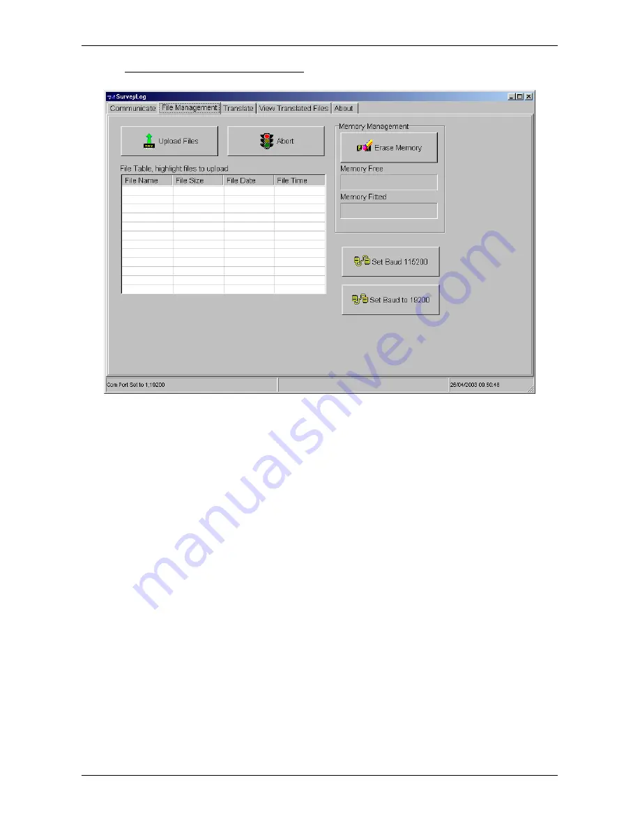
To upload large files, it is advisable to use a higher baud rate to minimise the upload time.  Use the Set Baud 

115200 button to change the baud rate of both PC and instrument. 


Highlight the data files of interest using the mouse; the standard Windows protocol of using Ctrl and Shift to select 

multiple files applies. 


Click the Upload Files button.  The data files will be automatically uploaded into a subdirectory of the SurveyLog 

program directory as follows: 

C:\Program Files\SurveyLog\program\Surveyor\

{ddmmyyyy}


The files will be named FILE????.bin, where ???? signifies the file number. 


Once the files have been uploaded, the memory may be erased by clicking on the Erase Memory button.  DO THIS 

WITH CAUTION!  Once erased, data files cannot be recovered, so be sure that all required files have been successfully 

uploaded with no data corruption.  The file upload protocol used is “Zmodem with error correction”, which is an extremely 

robust communications protocol.  As such, data corruption is very rare, but for important files it is advisable to view the 

data and confirm that upload has been successful before erasing the memory. 


Further data viewing does not require the MIDAS Surveyor to be connected to the PC.  If the baud rate has been 

increased for data upload purposes, it can now be reset by clicking the “Set Baud 19200” button.  Note that the button 

will revert the baud rate to whatever it was before it was increased. 


To return the instrument to normal operating mode, it is necessary to click the Run Surveyor button on the opening 

“Communicate” page.  Once this is done, the MIDAS Surveyor may be disconnected from the PC. 


Summary of Contents for MIDAS Surveyor

Page 1: ...e Company This document must not be copied reprinted or reproduced in any material form either wholly or in part and the contents of this document and any method or technique available therefrom must...

Page 2: ...ameters 15 4 2 3 5 Sound Velocity Interval 15 4 2 3 6 Tide Interval 16 4 2 3 7 Auxiliary Interval 16 4 2 4 RS232 Com Ports 16 4 2 5 Output Setup 17 4 2 6 Display setup 19 4 2 6 1 LCD delay 19 4 2 6 2...

Page 3: ...con Frequency 29 4 2 13 5 Echo External RTCM 29 4 2 14 Command Mode 29 4 2 15 Power Off 29 5 SURVEYLOG SOFTWARE 30 5 1 Introduction 30 5 2 Installation 30 5 3 Establishing Communications 31 5 4 File M...

Page 4: ...PS receiver Valeport offer a choice of two industry standard GPS receivers an Ashtech A12 twelve channel DGPS receiver or a high accuracy Ashtech DG16 sixteen channel DGPS receiver Both receivers feat...

Page 5: ...te FLASH memory holds approximately 30 hours data Optional 32Mbyte FLASH memory 2 2 TRANSDUCERS 2 2 1 HIGH FREQUENCY Frequency 210kHz 200kHz option Accuracy greater of 0 01m or 0 02 reading Resolution...

Page 6: ...Control Manual or Automatic set through MIDAS Surveyor 2 4 CONNECTORS 11 9 7 5 3 1 2 4 6 8 10 12 1 GPS antenna 2 LF Echosounder transducer 3 HF Echosounder transducer 4 External DC input Red Charging...

Page 7: ...ally downwards If anything the transducer should point a degree or two forward of vertical to help eliminate any cavitation effects at higher speed The combined transducer should be fitted with the sl...

Page 8: ...a field deployment The system is designed so that it will always draw its operating power from these internal batteries The system is supplied with an external DC input lead which should be used to c...

Page 9: ...ly assume that it is better than the standard SBAS correction and will use it instead If a full external GPS input is used the internal GPS receiver should be disabled as described in Section 4 2 10 1...

Page 10: ...mpensate for the GPS antenna being sited at a different location to the echosounder transducer The user is invited to enter this offset value during the system setup see Section 4 2 10 4 but this offs...

Page 11: ...ated pressing or pressing and holding darkens contrast When maximum contrast is reached the next press will revert to minimum contrast Help Causes a text message to be displayed on screen describing t...

Page 12: ...o do so although it will begin a new data file 4 1 RUN MODE The basic Run screen is indicated above and may be described as follows Bottom line of text Function keys and warning messages F1 Log On Off...

Page 13: ...instrument has been used or it is being used in a new location or configuration it is strongly advised that the each of the System Setup functions are viewed and changed as appropriate This applies pa...

Page 14: ...ways Turns instrument off 4 2 3 LOGGING SETUP The Logging Setup sub menu includes the following features 4 2 3 1 Log On Off This will allow the user to turn the data logging function on and off Access...

Page 15: ...Corrected Depth value only CORR HEAVE Corrected Depth value and Heave input COR HVE TID Corrected Depth value together with Heave and Tide values CORR TIDE Corrected Depth value and Tide input If Real...

Page 16: ...a points from this input to be logged to memory Use up and down arrows to scroll through the logging interval in 1 second increments from OFF through to 300 seconds 5 minutes and F3 to confirm Note th...

Page 17: ...type 0 Invalid or not available 1 Autonomous uncorrected position 2 RTCM or SBAS differentially corrected d2 Number of satellites used in position computation f1 Horizontal dilution of precision HDOP...

Page 18: ...ms may be blank F fathom label cc Checksum Example SDDBS f 088 98 M F 3D DBT SDDBT aaaaa f bbbbb m ccccc F cc where SDDBT identifier DBT Depth Below Transducer NB Surveyor draft value is NOT added to...

Page 19: ...ol the full data input string from any single chosen parameter may be displayed across the bottom of the screen Use the up down keys to scroll through the available options and Enter to confirm Off No...

Page 20: ...0000 Y axis rotational position 0 000000 Z axis rotational position 0 000000 XYZ Datum Scale Factor 0 0000000 Note that some spheroid references give an E figure instead of Flattening E stands for Ecc...

Page 21: ...anging these large numbers is different to that thus far encountered it would take a long time to scroll up or down to the required value The method described below applies to all of the parameters de...

Page 22: ...5m with Enter to confirm The unit is set to a factory default of 0 5m draft for both high and low frequency transducers 4 2 8 4 Metres Feet The MIDAS Surveyor may display data in either metres or dec...

Page 23: ...en logging and displaying of RAW or CORRECTED data Up down to toggle Enter to confirm 4 2 9 GPS SETUP 4 2 9 1 GPS Type The MIDAS Surveyor is supplied as standard with an integral 12 channel GPS receiv...

Page 24: ...ntered Use up or down to toggle between Heading from GPS and Heading from Auxiliary Input 4 2 10 SENSOR SETUP This section of the menu allows the user to setup the Surveyor to receive data from other...

Page 25: ...e logged as it is received However if it is a gyrocompass that is connected to this port you can choose whether to take the Surveyor heading display from this or from the GPS input As usual use up dow...

Page 26: ...vailable when the clock is set the entered values for minutes and seconds will be used instead and corrected as soon as there is a fix The assumption is that surveying will not begin until a valid GPS...

Page 27: ...on an arbitrary scale from 0 OFF to 10 approximately 1 5 seconds Use up and down to scroll up and down the range and Enter to confirm Access to the relay switch is gained by splicing the required wir...

Page 28: ...t settings Scroll to Reset All Defaults and press Enter The system will shut down and when it is turned on again all default settings will have been restored In summary these are Single channel only I...

Page 29: ...13 5 Echo External RTCM When setting up a Marine Beacon input it may be desirable to confirm that the receiver is actually picking up a signal Selecting this particular test mode will force any incomi...

Page 30: ...t although SurveyLog offers a variety of data display modes it offers no data editing features so users may wish to use a standard hydrographic survey package for data manipulation 5 2 INSTALLATION As...

Page 31: ...u button on the keypad Scroll to the third option down Data Upload Press the Enter button twice to accept this The screen should change to the Data Upload mode screen In SurveyLog select the appropria...

Page 32: ...n the Erase Memory button DO THIS WITH CAUTION Once erased data files cannot be recovered so be sure that all required files have been successfully uploaded with no data corruption The file upload pro...

Page 33: ...ly as it was logged with no data processing or interpolation occurring To allow the data to be viewed as graphical and time series plots all data points must be correctly time stamped This requires a...

Page 34: ...view the logged data exactly as it was recorded with no processing or interpolation simply click the View Translated ASCII File button A standard Windows Open File dialog box will appear Select the re...

Page 35: ...al grid Northing local grid Data count housekeeping purposes only normally 8 or 9 Type of Fix 0 No Fix 1 Uncorrected Fix 2 Differentially Corrected Fix SBAS or Beacon 3 RTK data external input only Nu...

Page 36: ...red from false echoes SurveyLog allows such points to be ignored in Valeport and XYZ files Simply set the lower and upper limits for valid data points before clicking on either the View Translated VAL...

Page 37: ...ate and time are calculated by linear interpolation between the GPS lines For example if there are 6 depth readings between successive GPS lines which are one second apart they will be time stamped 1...

Page 38: ...View Translated HF XYZ File or V View Translated LF XYZ File as appropriate To view the text data of the XYZ file click the XYZ data tab Again this data may be copied and pasted into other packages bu...

Page 39: ...with Fix Mark annotations click the XY plot tab This graph shows the survey track with the X axis corresponding to Longitude and the Y axis to Latitude The Fix Mark annotations are numbered sequential...

Page 40: ...C08 Echo Sounder Line Connector to Junction Box 0420C09 Echo Sounder 33KHz Transducer to Junction Box 0420C10 Echo Sounder 210KHz Transducer to Junction Box 0420C11 External Power Charger Lead 0420C12...

Page 41: ...ANA PLUGS POWER IN LINECONNECTOR POWER IN 9 WAY D TYPE HEAVE LINECONNECTOR HEAVE DATA LINECONNECTOR DATA COMMS TIDE LINECONNECTOR TIDEHEIGHT EXT E S LINECONNECTOR EXT ECHO SOUNDER SVP LINECONNECTOR SV...

Page 42: ...210KHz CABLEFORM No 0420C09B CABLEFORM NAME Echo Sounder 33KHz TRANSDUCER to Junction Box PRODUCT Midas Surveyor DRAWN BY D LAKIN CABLE END 1 END 2 FUNCTION WIRE TYPE WIRE COLOUR WIRE LENGTH mm Transd...

Page 43: ...INSTRUMENT COMMS LEAD PRODUCT Midas Surveyor heave Tide depth SVP aux gyro GPS DRAWN BY D LAKIN CABLE END 1 END 2 END 3 FUNCTION WIRE TYPE WIRE COLOUR WIRE LENGTH mm 7 Way Male Line Connector Fischer...

Page 44: ...cher PIN SINGLE POLE 1 WAY SWITCH PIN Supplied by Fischer 7 CORE SCREENED 24AWG 6 2mm MAX DIAMETER PROP785 BIPTN AF507 SCREEN 2000 SE103A056 130 6 2 1 RS 373 1640 SCREEN BLACK 2 RELAY 21 WHITE 3 A FIX...

Page 45: ...1 END 2 FUNCTION WIRE TYPE WIRE COLOUR WIRE LENGTH mm Marine Beacon 6 way connector PIN Junction Box PIN 6 CORE SCREENED FLYING LEAD BLACK As supplied 6 Way female as supplied 1 Connector block 1 Powe...

Page 46: ...cable spar clamp for A12 SBAS GPS Beacon antenna c w 5m cable spar clamp for DG16 SBA 1 IALA Beacon receiver antenna c w 5m cable spar clamp 210kHz transducer c w 10m cable bracket clamp 33kHz transdu...

Page 47: ...by any repair or attempted repair or dismantling by any one other than Valeport Limited or persons authorised to do so by Valeport Limited 3 Batteries and other consumables supplied with the equipmen...

Reviews: