78
Installation Instructions VRC 630 0020095108_00
7 Operating the controller
7.5 Exiting
the
Installer level
The Installer level is automatically disabled after approx.
60 minutes. You can view the system-specific parame-
ters in the Installer level at any time again.
7.6
Service functions
7.6.1
Operating sequence for service functions
The service functions are reserved for the heating engi-
neer.
You can call up the service functions from any of the
displays at any time.
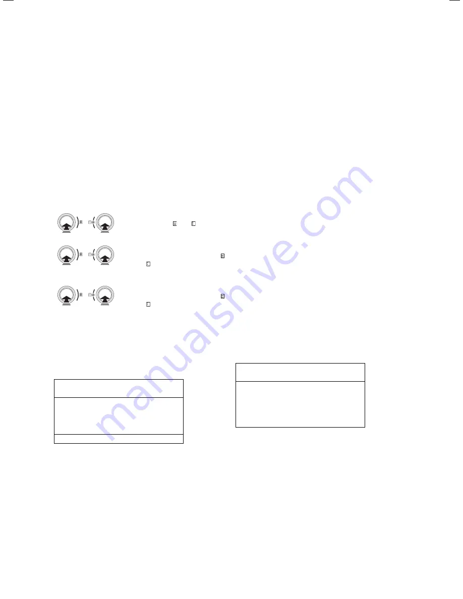
When you call up the service functions, you must always
follow a linear operating sequence:
Activate the maximum output
function by simultaneously
pressing the and knobs
once
>
Activate the manual mode by
simultaneously pressing the
and knobs once
>
End the service functions by
simultaneously pressing the
and knobs once
>
7.6.2
Maximum output operation
The maximum output function is necessary for emissi-
ons measurement.
Wed 02.12.09
15:43
-3 °C
Maximum output function
activated
Heating appliance
1
i
The selection of heating appliances (shown in
grey) is only possible with switching boilers.
i
The method for activating and terminating
the
maximum output function
is described
in the Operating Sequence for Service Func-
tions.
Activate maximum output operation by activating the
maximum output function.
Follow the operating sequence for service functions
when doing this (
¬
Chap. 7.6.1
)
The system is put into operation for a period of
20 minutes regardless of the set timer programme and
the outside temperature.
The boilers are activated depending on the heating
appliance used.
With modulating heating appliances, all connected hea-
ters are switched off by the controller and must be
directly put into operation at the heater (with the availa-
ble switch for chimney sweeper operation mode).
Observe the manuals for the boilers.
With switching boilers, select from the menu the boiler
for which the emissions measurement is to be carried
out. All remaining units are switched of in the meantime.
In maximum output mode the controller automatically
starts up the connected heating circuits. The controller
starts with the heating circuit with the highest maximum
temperature set. A further heating circuit is activated,
depending on the heat consumption. The switch-on cri-
terion is the flow temperature.
If the flow sensor at the collector sensor exceeds 80 °C,
the next heating circuit is switched on to ensure the
heat consumption.
7.6.3
Manual operation
Manual operation is required for functional testing of
the system.
Wed 02.12.09
15:43
-3 °C
Manual operation
activated
i
The method for activating and terminating
the manual mode is described in the Opera-
ting Sequence for Service Functions.
This function actuates all pumps of the system and the
heaters. The mixers remain in their last position.
7.7
Activating the special functions
Special functions are called up from the basic display.
>
>
>
Summary of Contents for VRC 630
Page 1: ...GB VRC 630 3 ...
Page 2: ......
Page 54: ......
Page 55: ...For the heating engineer Installation Manual VRC 630 ...
Page 152: ...0020095108_00 GB 022010 Subject to alterations ...


