5.5
Connecting
accessories
The following accessories can be connected:
Up to eight remote control devices to control the first
eight heating circuits.
Up to six mixer modules to extend the system by 12
system circuits (factory pre-set as mixer circuits).
5.5.1
Connecting the remote control device
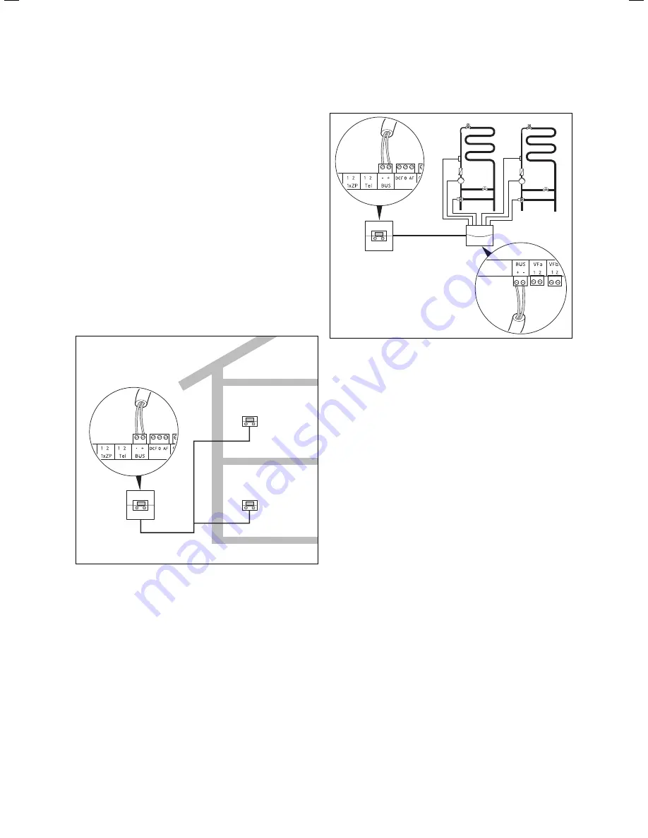
The remote control devices communicate with the hea-
ting controller via eBus. They can be connected to any
interface in the system. It simply has to be ensured that
the bus interfaces are eventually connected to the cen-
tral controller.
The structure of the Vaillant system allows you to run
the eBus from component to component (
¬Fig. 5.8
).
This means that the cables can be interchanged without
impairing communication.
eBUS
Fig. 5.12 Connecting remote control devices
All eBus connector plugs are designed to allow you to
wire at least 2 x 0.75 mm
2
per connection lead. We the-
refore recommend using 2 x 0.75 mm
2
for the eBus
lines.
–
–
5.5.2 Connecting further mixer circuits
eBUS
Fig. 5.13 Connecting further mixer circuits
Even the communication with the mixer modules takes
place only via the eBUS. The system structure is shown
in Fig. 5.13.
When installing, observe the same procedure as for
connecting the remote control units.
5.6
Connecting several heaters (cascade)
The control system permits a cascade connection of up
to:
8 boilers via VR 30 or VR 32 bus couplers
or
6 boilers via VR 31 bus couplers
within a system.
>
–
–
42
Installation Instructions VRC 630 0020095108_00
5 Electrical installation
Summary of Contents for VRC 630
Page 1: ...GB VRC 630 3 ...
Page 2: ......
Page 54: ......
Page 55: ...For the heating engineer Installation Manual VRC 630 ...
Page 152: ...0020095108_00 GB 022010 Subject to alterations ...


