89
Installation Instructions VRC 630 0020095108_00
Technical data 13
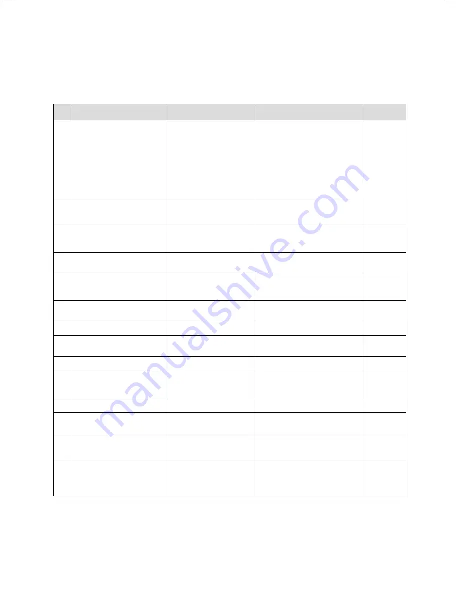
13.3
Factory settings
The factory settings can only be set, and if necessary
reset, in the Installer level.
Menu Displayed text
Settable parameters *)
Setting range
Factory set-
ting
C2
Heating circuit parameters
(
¬ Chap. 7.3.1
)
Set-back temperature
Heating curve
Max limit outs.temp.
Pump delay time
Minimum temperature
Maximum temperature
Max. pre-heat time
Switch-on room temperature
Fixed value day
Fixed value night
Max limit outs.temp.
Return temperature
5 - 30 °C
0.1 - 4
5 - 50 °C
0 - 30 min
15 - 90 °C
15 - 90 °C
0 - 300 min
None/Room temp./Thermostat
5 - 90 °C
5 - 90 °C
5 - 50 °C
15 - 60 °C
15 °C
1.2
21 °C
0 min
15 °C
75 °C/ 90 °C
0 min
None
65 °C
65 °C
21 °C
30 °C
C4
Cylinder charging circuit parame-
ters
(
¬ Chap. 7.3.3
)
Charging pump overrun
Parallel charging
Anti-legionella function
Legionella protect - start
0 - 15 min
Off/On
Off, Mon, Tue, ...Sum, Mon-Sun
00:00 - 24:00
5 min
Off
Off
04:00
C7
Overall system parameters
(
¬ Chap. 7.3.4
)
Max. pre-switch off
Frost protection delay
Continuous heating
Fast temperature increase
0 - 120 min
0 - 23 h
OFF, -25 ... 10°C
0 - 15 K
15 min
1 h
OFF
0 K
C8
Heating appliance parameters
(
¬ Chap. 7.3.5
)
Switching hysteresis
Minimum temperature
Cylinder starting output
1 - 20 K
15 - 90 °C
1 - 8
8 K
15 °C
1
C8
Heating appliance:
Cascade parameters
(only for cascade systems)
(
¬ Chap. 7.3.5
)
Switch on delay
Switch off delay
Reverse boiler sequence
1 - 60 min
1 - 60 min
Off/On
5 min
5 min
Off
C9
Special function - teleSWITCH
(
¬ Chap. 7.3.6.1
)
teleSWITCH for HK1 ... HK15
teleSWITCH for cylinders
None, Heating, Off, Auto, Eco, Energy
sav.
None, On, Off, Auto
Energy sav.
Off
C9
Special function - floor drying
(
¬ Chap. 7.3.6.2
)
Schedule HK2 ... HK15
0 - 29
0
C11
Service
(
¬ Chap. 7.3.7
)
Telephone number of service co.
Service date
Temp. fault detection after
0 - 9 (17-digit)
Date
Off, 0 - 12 h
–
1.1.2003
Off
C11
Changing the code level
(
¬ Chap. 7.3.7
)
Code Number
0000 ... 9999
C12
Tools
(
¬ Chap. 7.3.8
)
Temperature correction:
Outside temperature
Current room temperature
Display contrast
-5 ... +5 K
-3 ... +3 K
0 - 16
0 K
0 K
11
A1
Installation Assistant A1
Language selection (
¬ Chap. 7.4.1
)
Language
A4
Installation Assistant
System configuration
(
¬ Chap. 7.4.2
)
Number of boilers
Boilers are
Boilers at
1 or 2
1-stage or 2-stage
Stage 1-2 or 7, 8, 9
1
1-stage
7, 8, 9
A5
Installation Assistant
System configuration
(
¬ Chap. 7.4.3
)
Preference
Stop valves
Rev. seq control
Reverse boiler oeq.
YES/NO
YES/NO
YES/NO
OFF/ON
NO
NO
NO
OFF
A6
Installation Assistant
System configuration
(
¬ Chap. 7.4.4
)
HK1
HK2 ... HK15
Cylinder
Direct circuit, disabled
Direct or mixer circuit/Fixed value/
Return flow boost/Cylinder charging cir-
cuit/disabled
Cylinder charging circuit/, disabled
Direct circuit
Mixer circuit
Cylinder
charging circuit
Table 13.4 Factory settings
*) Which parameters are actually displayed in the menu depends
on the compnents connected and the settings.
Summary of Contents for VRC 630
Page 1: ...GB VRC 630 3 ...
Page 2: ......
Page 54: ......
Page 55: ...For the heating engineer Installation Manual VRC 630 ...
Page 152: ...0020095108_00 GB 022010 Subject to alterations ...


