Appendix
0020224355_00 HOME Installation and maintenance instructions
41
H
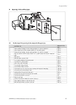
Opening in the air/flue pipe
G
N
N
M
M
A
II
O
H
H
C
B
L
J
Q
Q
Q
Q
Q
K
P
D, E
F
I
S
R
T
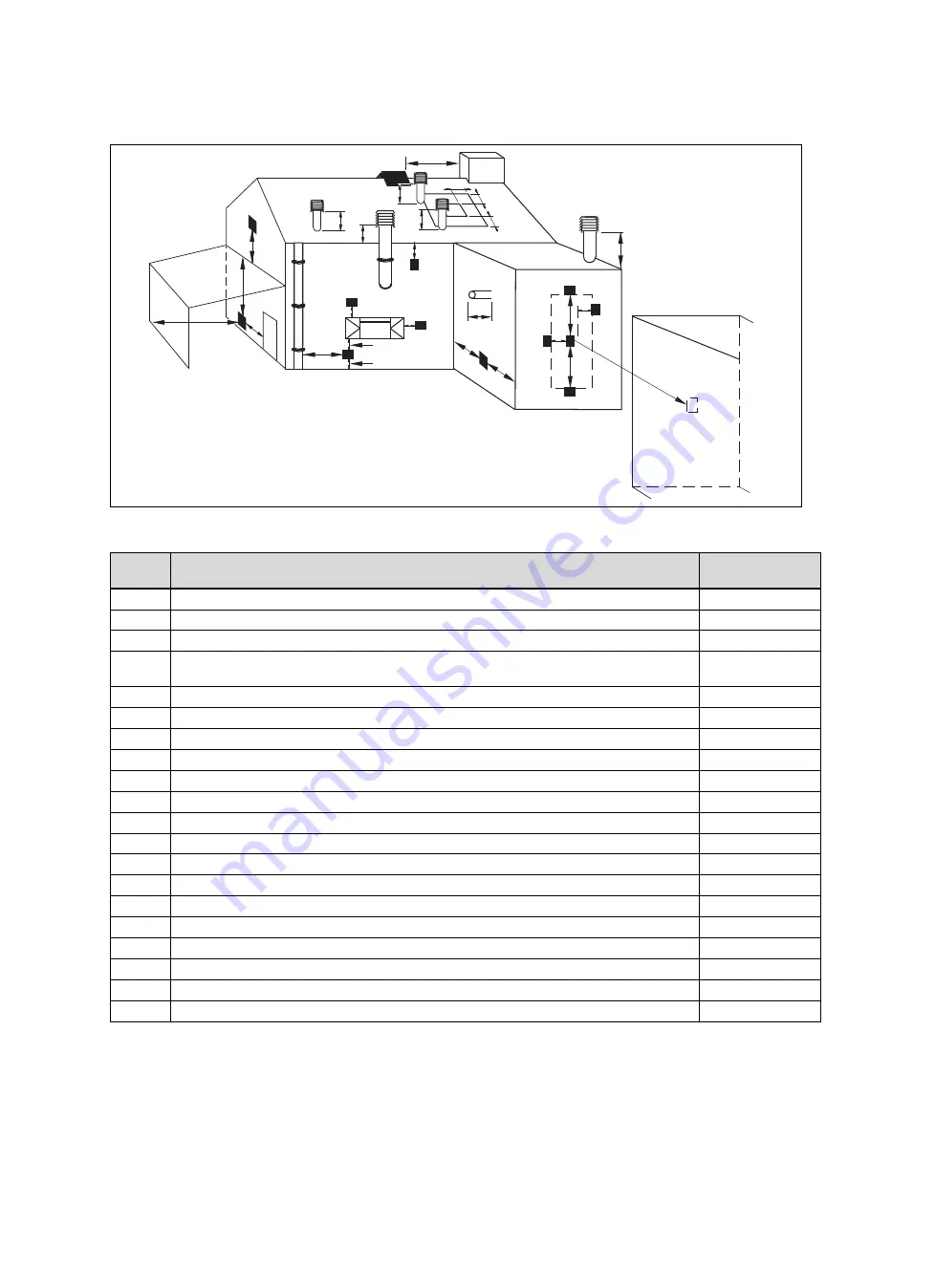
H.1
Positioning of the opening of a fan-supported flue gas pipe
Installation site
Minimum dimen-
sions
A
Directly below an opening, air bricks, opening windows, etc., that can be opened.
300 mm
B
Above an opening, air bricks, opening windows, etc., that can be opened.
300 mm
C
Horizontally to an opening, air bricks, opening windows, etc., that can be opened.
300 mm
D
Below temperature-sensitive building components, e.g. plastic gutters, down pipes or wastewater
pipes
75 mm
E
Below eaves
200 mm
F
Below balconies or car port roofs
200 mm
G
From vertical wastewater pipes or down pipes
150 mm
H
From external or internal corners
200 mm
I
Above floors, roofs or balconies
300 mm
J
From a surface facing a terminal
600 mm
K
From a terminal facing a terminal
1,200 mm
L
From an opening in the car port (e.g. door, window) which leads into the dwelling
1,200 mm
M
Vertical from a terminal on the same wall
1,500 mm
N
Horizontal from a terminal on the same wall
300 mm
O
From the wall on which the terminal has been installed
0 mm
P
From a vertical structure on the roof
N/A
Q
Above the roof area
300 mm
R
Horizontal from adjacent windows on pitched or flat roofs
600 mm
S
Above adjacent windows on pitched or flat roofs
600 mm
T
Below adjacent windows on pitched or flat roofs
2,000 mm
Summary of Contents for home combi
Page 51: ......

