5 Installation
12
Installation and maintenance instructions HOME 0020224355_00
5.4
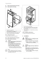
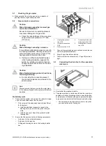
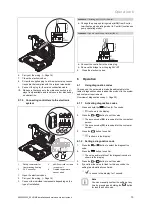
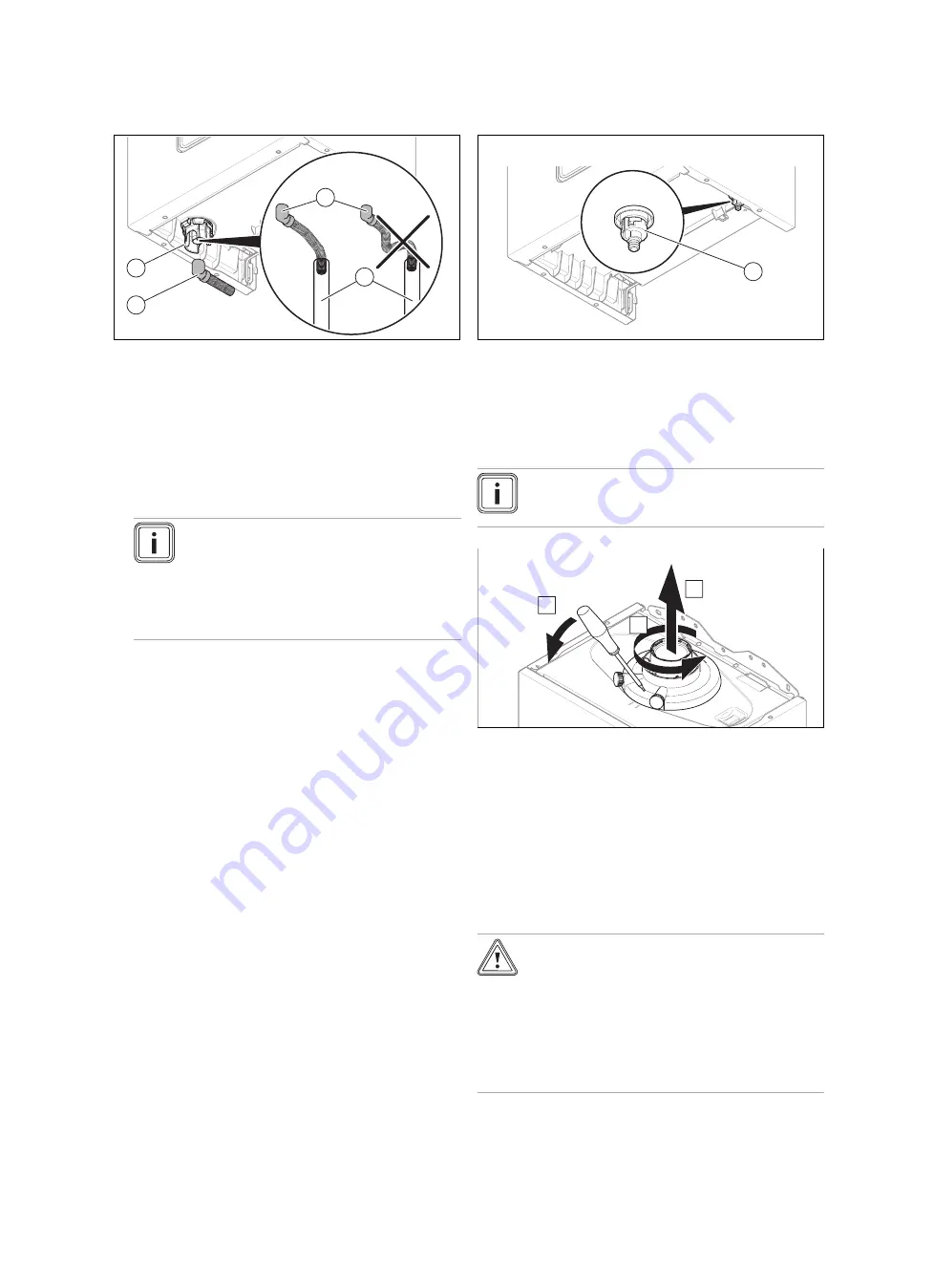
Connecting the condensate drain pipework
1
2
3
2
▶
Follow the instructions listed here and observe any legal
directives and local regulations on condensate discharge.
▶
Use PVC or another material that is suitable for draining
the non-neutralised condensate.
▶
If you cannot guarantee that the materials from which
the drain lines are made are suitable, install a system for
neutralising the condensate.
▶
Ensure that the connection between the condensate
drain pipework and the drain hose is not air-tight.
Note
The condensate drain pipework must have a
continuous fall (45 mm per metre) and should
whenever possible terminate at a suitable
drain point within the heated envelope of the
building that will remain frost free under long
periods of low external temperatures.
▶
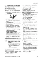
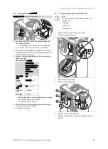
Connect the condensate siphon
(1)
. Use the supplied
drain hose
(2)
for this.
▶
Connect condensate drain pipework (21.5 mm, not in-
cluded in the scope of delivery)
(3)
to the drain hose
(2)
.
▶
During installation remove all burs from inside of cut pipe
work and avoid excessive adhesive which may trap small
pockets of water close to the pipe wall which can freeze
and build into a larger ice plug.
▶
As with other pipe work insulate the condensate dis-
charge pipe to minimise any risk of freezing and beware
when crossing cavities that the fall is maintained and the
pipe sleeved.
You can find further information in BS 6789: "Specification
for installing and maintaining gas-fired boilers with a nominal
heat loading less than 70 kW".
5.5
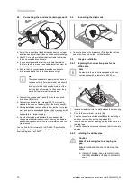
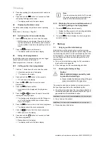
Connecting the drain cock
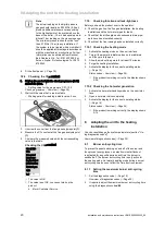
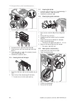
1
▶
Connect a hose to the drain cock
(1)
and guide the free
end of the hose to a suitable outflow location.
5.6
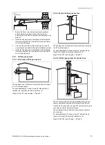
Flue gas installation
5.6.1
Replacing the connection piece for the
air/flue pipe
Note
As standard, the product is equipped with a con-
nection piece with a diameter of 60/100 mm.
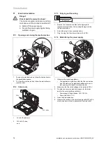
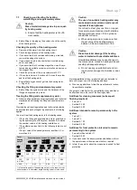
A
B
C
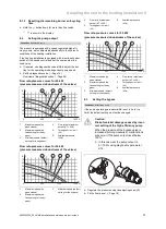
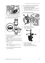
1.
Insert a screwdriver into the slot between the measuring
stub pipes.
2.
Push in the screwdriver carefully
(A)
.
3.
Turn the connector anticlockwise
(B)
as far as it will go
and then remove it by pulling it upwards
(C)
.
4.
Insert a new connector. In doing so, pay attention to the
latching lugs.
5.
Turn the connection piece clockwise so that it clicks into
position.
5.6.2
Installing the air/flue pipe
Caution.
Risk of poisoning due to escaping flue
gas.
Mineral-oil-based greases can damage the
seals.
▶
Instead of grease, use only water or com-
mercially available soft soap to aid install-
ation.
Summary of Contents for home combi
Page 51: ......


