Installation 5
0020224355_00 HOME Installation and maintenance instructions
13
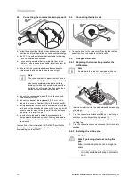
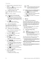
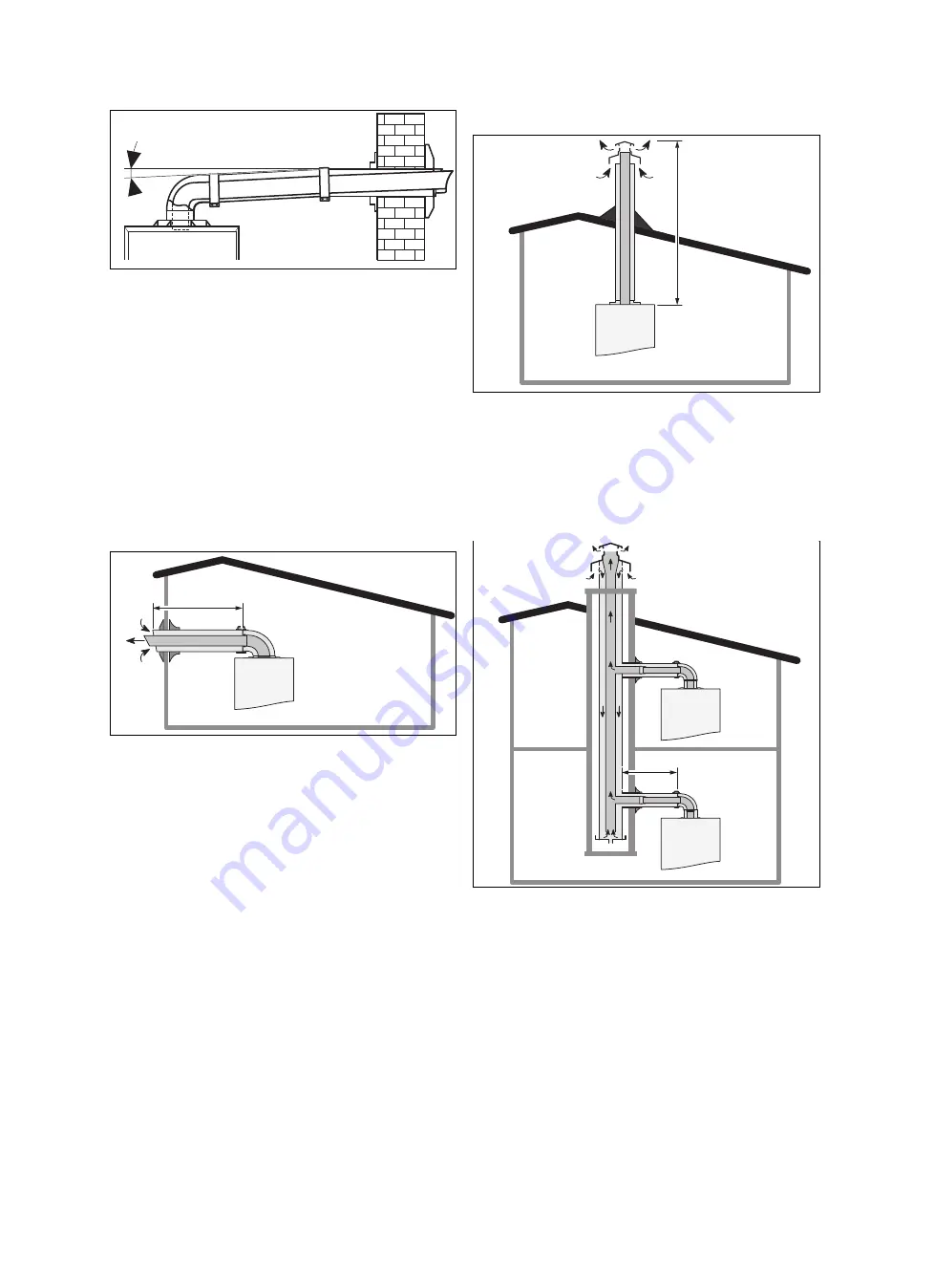
50 mm/1m
5 %
1.
Ensure that there is a minimum downward gradient
of 5% between the elbow and the terminal on the
air/flue pipe so that the condensate can flow back to the
product.
2.
Install the flue gas pipe in accordance with the installa-
tion instructions that are included in the scope of deliv-
ery for the air/flue pipe.
3.
You can find out which air/flue pipes may be used by
consulting the enclosed air/flue pipe installation manual.
4.
Install the flue gas pipe in accordance with the installa-
tion instructions that are included in the scope of deliv-
ery for the air/flue pipe.
5.6.3
Air/flue gas system
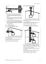
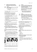
5.6.3.1 Horizontal air/flue gas system
L
The openings in an attachment for separate lines must lead
to a 50 cm-sided square.
For each additional 90° elbow (or two 45° elbows) that is
required, the length
(L)
must be reduced by 1 m.
Length of the C13 type flue pipe (
→
Page 47)
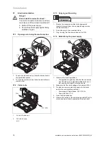
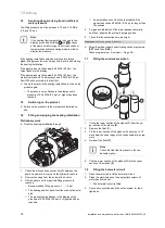
5.6.3.2 Vertical air/flue gas system
L
The openings in an attachment for separate lines must lead
to a 50 cm-sided square.
For each additional 90° elbow (or two 45° elbows) that is
required, the length
(L)
must be reduced by 1 m.
Length of the C33 type flue pipe (
→
Page 47)
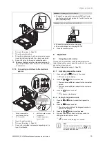
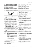
5.6.3.3 Air/flue gas system for header lines
L
The connections with the line are established using the ac-
cessory specially developed by the product manufacturer.
A boiler that is connected to a type C43 system must only be
connected to natural draught chimneys.
The condensate from header line systems must not drain
into the boiler.
For each additional 90° elbow (or two 45° elbows) that is
required, the length
(L)
must be reduced by 1 m.
Length of the C43 type flue pipe (
→
Page 47)
Summary of Contents for home combi
Page 51: ......


