Inspection and maintenance 10
0020244995_02
ecoTEC
pro
Installation
and
maintenance
instructions
27
Note
Instead of grease, use only water or com-
mercially available soft soap to aid installa-
tion.
13. Insert the flow and return connections into the heat
exchanger as far as they will go.
14. Make sure that the brackets are seated correctly on the
flow and return connections.
15. Install the compact thermal module. (
→
Page 29)
16. Fill and purge the product and, if necessary, the heating
installation. (
→
Page 19)
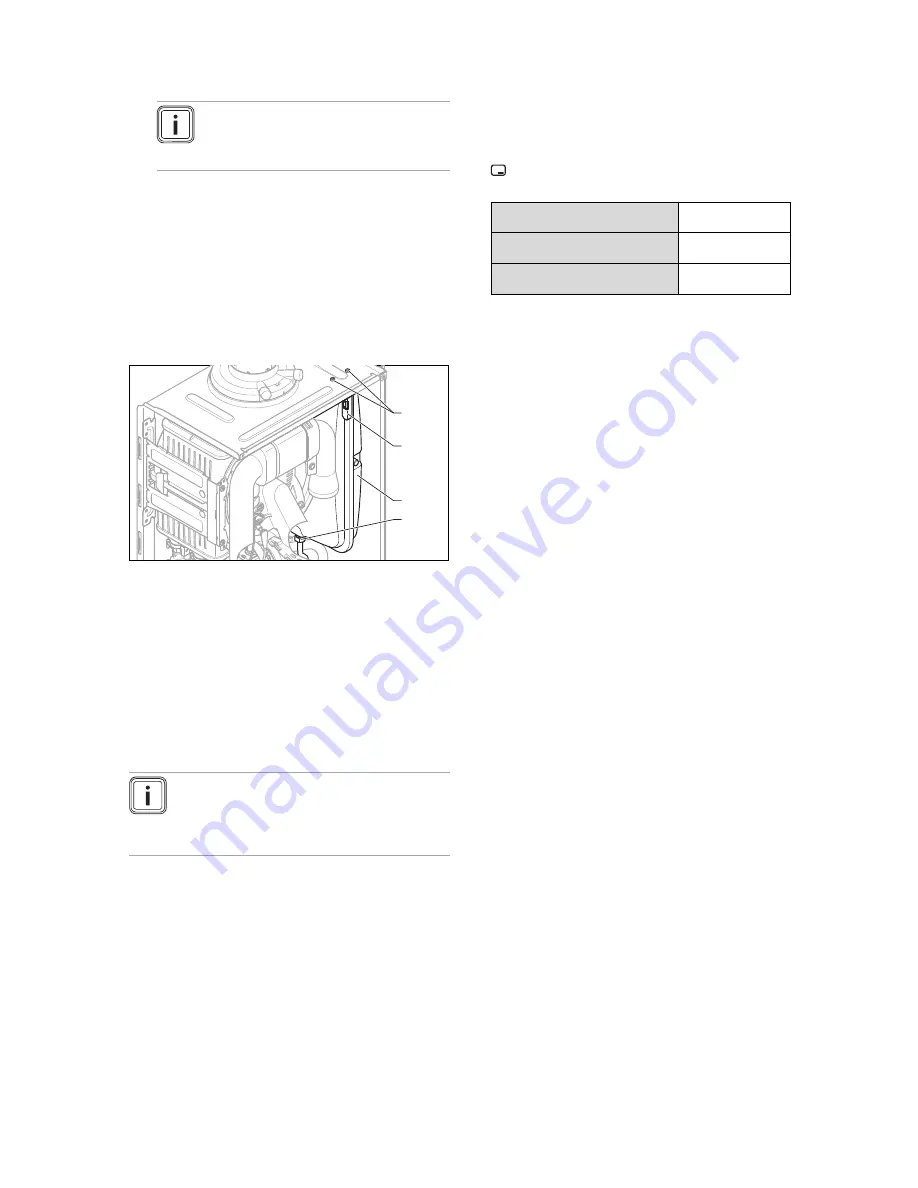
9.6.4
Replacing the expansion vessel
1.
Drain the product. (
→
Page 30)
1
2
3
4
2.
Undo the screwed connection
(4)
.
3.
Remove both screws
(1)
on the support plate
(2)
.
4.
Remove the support plate
(2)
.
5.
Pull out the expansion vessel
(3)
towards the front.
6.
Insert the new expansion vessel into the product.
7.
Screw the new expansion vessel to the water connec-
tion. Use a new seal for this.
8.
Attach the support plate using both screws
(1)
.
9.
Fill and purge the product and, if necessary, the heating
installation. (
→
Page 19)
9.6.5
Replacing the PCB or the display
Note
If you only replace one component, when the
product is switched on, the new component ad-
opts the parameters that were previously set from
the component that was not replaced.
1.
Open the electronics box. (
→
Page 15)
2.
Replace the PCB or display according to the assembly
and installation instructions supplied.
3.
Close the electronics box.
9.6.6
Replacing the PCB and the display
1.
Open the electronics box. (
→
Page 15)
2.
Replace the PCB and display according to the
assembly and installation instructions supplied.
3.
Close the electronics box.
4.
Press the on/off button on the product. (
→
Page 18)
◁
You are automatically taken to
D.093
to set the
device specific number.
5.
Set the correct value for the relevant product type in ac-
cordance with the table below and confirm by pressing
.
Product type number
VUW 246/5-3 (H-GB) ecoTEC pro
24
7
VUW 286/5-3 (H-GB) ecoTEC pro
28
22
VUW 286/5-3 (P-GB) ecoTEC pro
28
22
◁
The electronics are now set to the product type and
the parameters of all diagnostics codes are set to
default settings.
6.
Make the system-specific settings.
9.7
Completing repair work
1.
Establish the power supply.
2.
Switch the product back on if this has not yet been
done. (
→
Page 18)
3.
Install the front casing.
4.
Open all service valves and the gas isolator cock.
9.8
Checking the product for leak-tightness
▶
Check that the product is leak-tight. (
→
Page 22)
10 Inspection and maintenance
▶
You must carry out an annual inspection of the product.
The annual inspection can be effectively performed
without removing components by requesting data from
the DIA system, carrying out the simple visual checks in-
dicated in the table in the appendix and performing a flue
gas measurement. The maintenance intervals and their
scope are determined by the heating engineer based on
the condition of the boiler found during the inspection. All
inspection and maintenance work should be performed in
the order specified in the table in the appendix.
During any inspection and maintenance or after change
of parts of the combustion circuit, the following must be
checked:
–
The boiler has been installed in accordance with the rel-
evant installation instructions.
–
The integrity of the flue gas installation and flue seals is
in accordance with the relevant flue installation instruc-
tions enclosed.
–
Visual, the integrity of the boiler combustion circuit and
relevant seals (paying particular attention to the burner
door seal).
–
The gas inlet working pressure at maximum rate.
–
The gas flow rates.
–
Correctness of electrical, water and gas connections.
–
Correctness of the water pressure.
–
The condition of the whole system, in particular the con-
dition of radiator valves, evidence of leakage from the
heating system and dripping taps.
▶
Correct any faults before proceeding.


