Installation Manual auroMATIC 560 0020060907_00
16
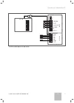
5.4 Hydraulic
plan
3
Kol 1
230 V
Kol1-P
Ertrag
Sp1
Sp2
EP
S
1
2
KW
LegP
Kol2P
Kol2
HZ
-K
HZ
-K
HZ
-K
C1 C2
C1 C2
C1 C2
230 V
I
II
III
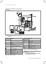
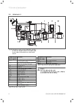
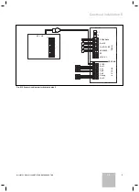
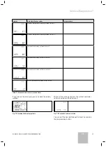
Fig. 5.11 Hydraulic plan 3 with system configuration: one collec-
tor array, one solid fuel boiler, one solar cylinder, option
for connecting to different heaters for reheating the
cylinder
Designation in the
hydraulic plan/con-
nection diagram
Component
I, II, III
Option for connecting to different heaters
for reheating the cylinder
C1 C2
Connections for controlling the heating ap-
pliances for recharging the cylinder
HZ-K
Heating circuit(s)
KW
Cold water
EP
Electric heating element (optional)
Kol1-P
Solar circuit pump 1
Kol 1
Collector sensor 1
Kol2-P
Reheating pump 2
Kol 2
Reheating sensor 2
Ertrag
Yield
LegP
Legionella protection pump
Sp1
Cylinder sensor 1
Sp2
Cylinder sensor 2
S
Contactor
1
Contactor control for optional electric heat-
ing element
2
400 V connection, 3-phase
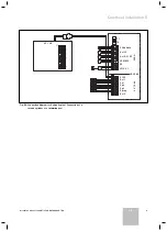
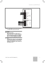
Table 5.7 Key to Fig. 5.11 and Fig. 5.12
Designation in the
hydraulic plan/con-
nection diagram
Component
230 V
230 V mains connection
F1 (T4)
Fuse holder
VC/VK
Connection area for boiler
Table 5.7 Key to Fig. 5.11 and Fig. 5.12 (continuation)
H
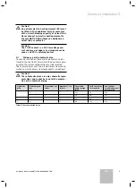
Danger
Risk of scalding by hot water
It is imperative that the mixer valve is fitted to
ensure protection from scalding.
5 Electrical installation
Summary of Contents for auroMATIC 560
Page 1: ...auroMATIC 560 VRS 560 ES GB ...
Page 2: ......
Page 4: ......
Page 16: ......
Page 44: ......
Page 46: ......
Page 84: ...0020060907_00 ESGB 122007 ...


