9
Operating Manual auroMATIC 560 0020060907_00
GB
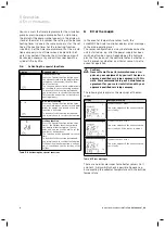
5.4 Display
modes
5.4.1
Main operating level display
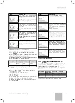
When you switch the unit on, the main operating level
appears initially. Section 5.5.2 describes how to set and
change the values.
1
2
4
5
6
3
Fig. 5.3 Main operating level display
Key
1
Indication that solar yield is available
2
Actual collector temperature
3
Current time of day or, if active,
LEG for anti-Legionella function
FROS Frost protection function
PROT Solar circuit protection function
4
Current day of the week
5
Actual cylinder temperature (the target temperature can be
called up and adjusted by turning the dial)
6
Current operating mode
5.4.2 Info level display
You can access the info level by pressing the Info button.
First, the display illustrated below appears. You can call
up further information by repeatedly pressing the Info
button (see Section 5.5.1). The information called up in
each case is visible in the display for approximately
five seconds, after which the display reverts to the main
operating level.
1
2
4
3
Fig. 5.4 Info level display
Key
1 Info
level
2 Solar yield indicator
3 Yield in kWh
4 Cylinder target temperature
5.4.3 Programming level display
You can access the level for programming the controller
switching times by pressing on programming button P.
Here you can set the timer programmes for reheating
the solar cylinder and for a circulation pump when con-
nected (see Section 5.5.3 or 5.5.4).
The display reverts to the main operating level when you
press the programming button.
1
2
4
5
6
3
7
Fig. 5.5 Programming level display
Key
1 Programming
level
2 Timer programme for solar cylinder reheating
(water tap symbol) or the circulation pump
(pump symbol)
3 Stop
time
4 Start
time
5 Day of the week or block of days
6 Cursor (marks the value to be changed)
7 Window
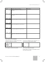
5.4.4 Special functions display
You can access the advance, one-time reheat and holi-
day special functions by pressing the F button. The se-
lected function will be activated after approximately
ten seconds and the display will revert to the main oper-
ating level.
The activation of the individual special functions is de-
scribed in Section 5.6.
1
2
3
Fig. 5.6 Special functions display
Key
1 Special function activated
2 Cursor (marks the selected special function)
3 Symbol for the selected special function
Operation 5
Summary of Contents for auroMATIC 560
Page 1: ...auroMATIC 560 VRS 560 ES GB ...
Page 2: ......
Page 4: ......
Page 16: ......
Page 44: ......
Page 46: ......
Page 84: ...0020060907_00 ESGB 122007 ...

