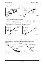
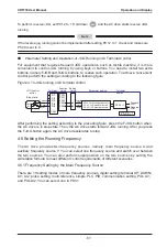
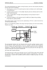
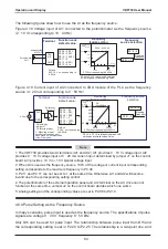
background image

VDF730


User


Manual


Operation


and


Display

73

 -

Figure


4

-

31


Communication


control


mode


of


the


AC


drive

Host 

computer

485

+

485

-

PA

-

00

Baud rate

PA

-

01

Data format

PA

-

02

Local address

PA

-

03

Response delay

PA

-

04

Communication


timeout

Function


code

Running status 
parameters

Running 
command

Modbus

-

RTU


communication 
protocol

RS485

The setting of communication


parameters


in


the AC


drive must be 

consistent


with


that in the


host computer

.

VDF730

The


VDF730


arranges


the


function


codes

running


state


parameters


and


running


commands


in


the

 "

register  parameter  address

mode

The  host


computer  can  defne


the


protocol  for


communication


data


interaction

.

4

.

13


Password


Setting

The


AC


drive


provides


the


user


password


protection


function

When


PP

-

00


is


set


to


a


non

-

zero  value

the  value  is  the  user  password

The  password  takes  effect  after  you  exit  the


function


code


editing


state

When


you


press


PRG

 again

, "------" 

will


be


displayed

and


you


must


enter


the


correct


user


password


to


enter


the


menu

.

To


cancel


the


password


protection


function

enter


with


password


and


set


PP

-

00


to


00000

.

4

.

14


Default


Initialization

After


a


function


code


is


modifed


on


the


operation


panel

the


modifcation


will


be


saved


in


the


register


of


the


AC


drive


and


remain


effective


at


next


power

-

on

.

The


AC  drive  also  provides  the retentive  function  on


alarm


information  and


accumulative


running


time

.

You


can


restore


default


settings


of


the


function


codes


or


clear


the


running


data


through


PP

-

01

For


details

see


the


description


of


PP

-

01

.

Figure


4

-

32


Parameter


saving


and


default


parameter


restoring

Function code


parameters


in


factory


backup


area


(

factory


parameters

)

Function code


parameters


in


work


area


during


running

Retentive at 
power

-

failure in


register


area

PB

-

20

PB

-

27

Fault


records

P7

-

12

Accumulative running time

(

PP

-

01 

1

) + 

ENTER

Restore default


setting

(

PP

-

01 

2

) + 

ENTER

Clear recorded


information manually

Power

-

on


running

(

PP

-

01 

3

) + 

ENTER

Clear the


power

-

on time

P5

-

43

P5

-

44

Power

-

on time

Certain parameters


cannot


be restored


to the


default


setting

Motor


parameters


in group P1

Accumulative running time
Inverter


module temperature

Fault


parameters

User


password

Summary of Contents for VDF730 Series

Page 1: ...VDF730 Series...

Page 2: ...series AC drive including selection parameter setting commissioning maintenance inspection Read and understand the manual before use and forward the manual to the end user Notes The drawings in the m...

Page 3: ...model and AC drive ratings are consistent with your order The box contains the AC drive certifcate of conformity user manual and warranty card Whether the AC drive is damaged during transportation If...

Page 4: ...the AC drive Select a proper circuit breaker to resist large in rush current that flows into the AC drive at power on Use within the allowable power supply specification of the AC drive Reduce the el...

Page 5: ...Warranty 26 2 8 Braking Component Selection Guideline 26 Chapter 3 Mechanical and Electrical Installation 30 3 1 Mechanical Installation 30 3 2 Electrical Installation 36 Chapter 4 Operation and Displ...

Page 6: ...Process Control PID Function 134 Group P7 Swing Frequency Fixed Length and Count 137 Group P8 Multi Reference and Simple PLC Function 141 Group P9 Reserved 144 Group PA Communication Parameters 144 Gr...

Page 7: ......

Page 8: ...1 Safety Information and Precautions...

Page 9: ...age component missing or damage upon unpacking Do not install the equipment if the packing list does not conform to the product you received DANGER Handle the equipment with care during transportation...

Page 10: ...ed cable for the encoder and ensure that the shielding layer is reliably grounded Before power on WARNING Check that the following requirements are met The voltage class of the power supply is consist...

Page 11: ...the residual voltage in the capacitor will result in personal injury Ensure that the AC drive is disconnected from all power supplies before starting repair or maintenance on the AC drive Set and che...

Page 12: ...which can be avoided by setting the skip frequency 7 Motor heat and noise The output of the AC drive is pulse width modulation PWM wave with certain harmonics and therefore the motor temperature nois...

Page 13: ...of three phase input changed into two phase input Do not change the three phase input of the AC drive into two phase input Otherwise a fault will result or the AC drive will be damaged 12 Surge suppr...

Page 14: ...fan or replace it with variable frequency motor in applications where the motor overheats easily The standard parameters of the adaptable motor have been confgured inside the AC drive It is still nece...

Page 15: ...Safety Information and Precautions VDF730 User Manual 14...

Page 16: ...2 Product Information...

Page 17: ...and Technical Data Table 2 1 VDF730 models and technical data VDF730 Model Input Voltage Power Capacity kVA Input Current A Output Current A Motor Power kW VDF730S0 4GB Single phase 220 V range 15 to...

Page 18: ...0 307 0 253 0 304 0 132 160 VDF730T160G 200P 250 0 385 0 304 0 377 0 160 200 VDF730T200G 220P 280 0 430 0 377 0 426 0 200 220 VDF730T220G 250P 355 0 468 0 426 0 465 0 220 250 VDF730T250G 280P 396 0 5...

Page 19: ...on or combination of DI terminal states Built in PID It implements the closed loop process control system easily Auto voltage regulation AVR It can keep constant output voltage automatically when the...

Page 20: ...and running frequency FM can also be used for AO output Display and operation on the operation panel LED display It displays the parameters and monitored state of the AC drive Protection function Moto...

Page 21: ...arance and Overall Dimensions of the VDF730 2 4 1 Product Appearance and Mounting Dimensions of the VDF730 Figure 2 2 Physical appearance and overall dimensions of the VDF730 VDF730S0 4GB to VDF730T15...

Page 22: ...183 5 0 VDF730T5 5GB 7 5PB VDF730T7 5GB 11PB 190 305 322 208 192 6 VDF730T11GB 15PB VDF730T15GB 18 5PB VDF730T18 5GB 22PB 160 400 382 415 220 212 7 VDF730T22GB 30PB VDF730T30G 37P VDF730T37G 45P 170...

Page 23: ...oduct Information VDF730 User Manual 22 2 4 2 Physical Dimensions and Mounting Dimensions of the External Operation Panel Figure 2 3 Mounting hole dimensions of the external operation panel 99 50 72 5...

Page 24: ...VDF730T110G 132P 160 190 125 161 192 255 195 10 x 15 12 DCL 0250 VDF730T132G 160P VDF730T160G 200P 160 190 125 161 192 255 195 10 x 15 12 DCL 0360 VDF730T200G 220P VDF730T220G 250P 190 230 93 128 250...

Page 25: ...to be confgured with an external braking unit Mulitple external braking units are connected in parallel for 55G 75P or above External LED operation panel without the potentiometer VDKE2 The external L...

Page 26: ...ion Perform periodic inspection on the items that are diffcult to check during running Periodic inspection involves Checking and cleaning the air flter periodically Checking whether the screws become...

Page 27: ...ltage must be increased slowly to the rated value with the regulator 2 7 Warranty 1 The warranty agreement applies only to the AC drive itself 2 The warranty period of the product is 18 months as of i...

Page 28: ...ula 0 7 x Pr Pb x D Pr refers to the power of resistor D refers to the braking frequency percentage of the regenerative process to the whole working process Application Elevator Winding and unwinding...

Page 29: ...T132G 160P 6 5 kW x 2 8 x 2 External VDBUN 90 T x 2 VDF730T160G 200P 16 kW 2 5 External VDBU 200 B VDF730T200G 220P 20 kW 2 5 External VDBU 200 B VDF730T220G 250P 22 kW 2 5 External VDBU 200 B VDF730T...

Page 30: ...3 Mechanical and Electrical Installation...

Page 31: ...2 Installation Clearance Requirements The clearance that needs to be reserved varies with the power class of the VDF730 as shown in the following fgure Figure 3 1 Clearance around the VDF730 for inst...

Page 32: ...30 series AC drives have two housing types plastic housing and sheet metal housing according to different voltage and power classes The VDF730 supports both wall mounting installation and embedded ins...

Page 33: ...c housing Figure 3 4 External hanging bracket for the VDF730 External hanging bracket Figure 3 5 Embedded installation of the VDF730 plastic housing Install the AC drive on the front of the control ca...

Page 34: ...tallation of the VDF730 sheet metal housing Install the AC drive on the front of the control cabinet Back panel of control cabinet Fix four screws Figure 3 8 Hoisting the VDF730 sheet metal housing 4...

Page 35: ...Figure 3 1 to ensure sufficient space for heat dissipation Take heat dissipation of other parts in the cabinet into consideration 2 Install the AC drives upright to facilitate heat dissipation If mult...

Page 36: ...e front cover and before wiring the main circuit and control circuit Figure 3 12 Removal of the front cover of the VDF730 plastic housing 1 Press inward symmetrically to disconnect the hook from the h...

Page 37: ...PB 25 25 4 0 4 0 0 75 VDF730T7 5GB 11PB 32 32 4 0 4 0 0 75 VDF730T11GB 15PB 40 40 6 0 6 0 0 75 VDF730T15GB 18 5PB 50 50 10 10 1 0 VDF730T18 5GB 22PB 50 50 10 10 0 75 VDF730T22GB 30PB 63 63 16 16 0 75...

Page 38: ...e output side of the AC drive Reduces the external conduction and radiation interference of the AC drive Decreases the conduction interference fowing from the power supply side to the AC drive and imp...

Page 39: ...rce 0 10 V Frequency source 0 10 V Single phase 220 V power supply RS485 port Interface for external operation panel J1 AI2 voltage current input selection J2 AI2 operation panel potentiometer selecti...

Page 40: ...4V FMP pulse output or open collector output Digital output U V W Ground PB DI1 DI4 DI3 DI5 DI2 COM 485 485 10V GND PE AI2 AI1 J2 J1 J3 J4 AO GND FM COM DO1 AI2 JP V I V I IN EXT QF R S T Interface fo...

Page 41: ...or open collector output Digital output U V W Ground DI1 DI4 DI3 DI5 DI2 COM A A 10V GND PE AI2 AI1 J2 J1 J3 J4 AO GND FM COM DO1 AI2 JP V I V I IN EXT QF R S T Braking unit Braking resistor Interface...

Page 42: ...e for external operation panel RJ45 DI1 DI2 DI3 DI4 DI5 DI1 J1 AI2 voltage current input selection J2 AI2 operation panel potentiometer selection J3 AO voltage current output selection J4 DI internal...

Page 43: ...asses Figure 3 18 Terminal layout of VDF730S0 4G VDF730S0 7G VDF730S1 5G and VDF730S2 2G Figure 3 19 Terminal layout of VDF730T0 7GB to VDF730T 7 5GB 11PB POWER U V W MOTOR R S T PB Figure 3 20 Termin...

Page 44: ...nstallation 43 Figure 3 21 Terminal layout of VDF730T22GB 30PB Figure 3 22 Terminal layout of VDF730T30G 37P to VDF730T37G 45P R S T POWER P U V W MOTOR B P Figure 3 23 Terminal layout of VDF730T45G 5...

Page 45: ...n Circuit Terminals Safety Information DANGER Peform wiring only after all power supply is cut off Failure to comply will result in electric shock Only qualifed personnal are allowed to perform wiring...

Page 46: ...nals of DC bus Common DC bus input points PB Connecting terminals of braking resistor Connect a braking resistor U V W AC drive output terminals Connect a three phase motor Grounding terminal Must be...

Page 47: ...raking unit The cable length of the braking resistor must be smaller than 5 m Otherwise it may damage the AC drive 4 Terminals P for connecting the external reactor For the AC drives of 75G 90P and ab...

Page 48: ...wer supply Provide 10 V power supply to the external unit Generally it provides power supply to the external potentiometer with resistance range of 1 5 k Maximum output current 10 mA 24V COM External...

Page 49: ...output DO1 COM Digital output Optical coupling isolation open collector output Output voltage range 0 24 V Output current range 0 50 mA FM COM High speed pulse output It is limited by P5 00 FM termin...

Page 50: ...ength must be less than 20 m as shown in following fgure Figure 3 24 Wiring mode of AI terminals 10 V AI1 GND Potentiometer PE 20 m VDF730 In applications where the analog signal suffers severe interf...

Page 51: ...Mechanical and Electrical Installation VDF730 User Manual 50...

Page 52: ...4 Operation and Display...

Page 53: ...F730 by operating the operation panel as shown in the following fgures RUN indicator Data display Programming key Shift key RUN key Stop Reset key Potentiometer for speed adjustment Increment key Decr...

Page 54: ...means that the indicator is ON and means that the indicator is OFF Hz A V RPM Hz unit of frequency Hz A V RPM A unit of current Hz A V RPM V unit of voltage Hz A V RPM RPM unit of rotational speed Hz...

Page 55: ...unction code group Level I function code Level II and function code setting value level III as shown in the following fgure Figure 4 3 Operation procedure on the operation panel P0 P0 03 5 Select the...

Page 56: ...p or running state you can press on the operation panel to display status parameters Whether parameters are displayed is determined by the binary bits of values converted from the values of P7 13 and...

Page 57: ...k 2 Set the corresponding bit of each parameter to be displayed to 1 3 Convert the binary data to a decimal value and set this value in P7 13 7 6 5 4 3 2 1 0 Low bits 15 14 13 12 11 10 9 8 High bits 0...

Page 58: ...tart stop 1 2 P0 00 1 Running command P2 06 0 Control switch Terminal Function code Setting value Terminal control COM RUN Forward Forward RUN Terminal control Command source selection Two line mode 1...

Page 59: ...l address PA 03 Response delay PA 04 Communication timeout The communication setting in the AC drive must be consistent with that in the host computer P0 00 2 Running command 485 485 RS485 VDF730 2000...

Page 60: ...limit P0 09 Acceleration time Frequency f Time t Running command Initial rotational speed of the load motor P4 00 1 Rotational speed tracking restart Automatic rotational speed tracking detection P0...

Page 61: ...run at a low speed temporarily to facilitate equipment test or other commissioning operations In this case you can set the AC drive to perform JOG running Figure 4 12 JOG running Running frequency f...

Page 62: ...meter setting Forward JOG Reverse JOG FJOG RJOG Reverse JOG P5 00 JOG running frequency P5 01 JOG acceleration time P5 02 JOG deceleration time Forward JOG Reverse JOG Stop state P5 09 1 After perform...

Page 63: ...ction codes manual adjustment analog input multi speed terminal external feedback signal internal PID regulator or the host computer Set the corresponding function codes of each frequency setting mode...

Page 64: ...y sources Auxiliary frequency source Y P0 05 P0 06 P0 18 Target running frequency Main frequency source X X Y 0 1 2 3 4 P2 00 to P2 04 33 DI1 to DI5 Frequency switchover X Y Frequency source selection...

Page 65: ...to0 50Hz P0 04 50 00Hz 16 0 12 0 8 0 4 0 100 0 P2 18 0 80 0 60 0 40 0 20 0 0 0 Corresponding setting Unit mA Unit V I Selection by jumper J1 AI2 GND Selection by jumper J1 I AI2current input V AI2volt...

Page 66: ...ction 0 Forward action 1 Reverse action P6 09 PID deviation limit PID1 Proportional gain P P6 06 Integral time I P6 07 Derivative time D P6 08 PWM drive Execution by motor Object Transmitter detection...

Page 67: ...P8 02 Reference 6 P8 07 Reference 2 P8 03 Reference 7 P8 08 In the preceding fgure DI3 DI2 and DI1 are used as the multi frequency input terminals each of which has a bit value The state combinations...

Page 68: ...nction codes because the function codes will be restored once the AC drive restores the default settings 4 6 9 Setting the Fixed Length Control Mode The VDF730 has the fxed length control function The...

Page 69: ...DI terminal that is allocated with function 23 When the count value reaches P7 08 Set count value the DO terminal allocated with function 10 Set count value reached becomes ON Then the counter stops c...

Page 70: ...730 AC drive adopts V F mode to drive the motor Accurate motor parameters are required to ensure desired driver performance and running efficiency Set the motor parameters according to the nameplate M...

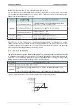
Page 71: ...a decimal value The AC drive also provides P2 05 DI filter time for the DI signal to improve the anti interference level The five DI terminals can be defined in function codes P2 00 to P2 04 Each DI...

Page 72: ...al running parameters The greater the value is the higher the output pulse frequency is The 100 value corresponds to 100 kHz The property of the indicated internal parameter is defned by P5 06 4 10 Us...

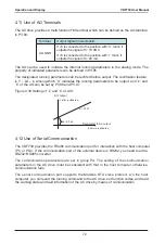
Page 73: ...o be output and k and b of the AO can be set by P3 06 and P3 07 Figure 4 30 Setting of k and b of AO1 K P3 07 Parameter to be output AO output Y after rectification X before rectification b P3 06 4 12...

Page 74: ...enter the menu To cancel the password protection function enter with password and set PP 00 to 00000 4 14 Default Initialization After a function code is modifed on the operation panel the modifcation...

Page 75: ...Operation and Display VDF730 User Manual 74...

Page 76: ...5 Function Code Table...

Page 77: ...odifed The parameter is factory parameter and can be set only by the manufacturer Function Code Parameter Name Setting Range Min Unit Default Property Group P0 Basic Parameters P0 00 Command source se...

Page 78: ...del dependent P0 10 Deceleration time 1 0 00 300 00s m 0 01s m Model dependent P0 11 Carrier frequency 0 5 16 0 kHz 0 1 kHz Model dependent P0 12 Rotation direction 0 Same direction 1 Reverse directio...

Page 79: ...0 01 Hz 0 00 Hz P0 21 Carrier frequency adjustment with temperature 0 No 1 Yes 1 1 P0 22 Binding command source to frequency source Unit s digit Binding operation panel command to frequency source 0 N...

Page 80: ...1 P1 0 00 Hz to P1 09 0 01 Hz 0 00 Hz P1 08 Multi point V F voltage 1 v1 0 0 100 0 0 1 0 0 P1 09 Multi point V F frequency 2 P2 P1 07 to P1 11 0 01 Hz 0 00 Hz P1 10 Multi point V F voltage 2 v2 0 0 1...

Page 81: ...ult 12 Normally closed NC input of external fault 13 Multi reference terminal 1 14 Multi reference terminal 2 15 Multi reference terminal 3 16 Terminal for acceleration deceleration time selection 17...

Page 82: ...nd mode 0 Two line mode 1 1 Two line mode 2 2 Three line mode 1 3 Three line mode 2 1 0 P2 07 Terminal UP DOWN rate 0 01 100 00 Hz s 0 01 Hz s 1 00 Hz s P2 08 AI1 minimum input 0 00 V to P2 10 0 01 V...

Page 83: ...rresponding setting mode of pulse maximum input 0 P2 24 1 Determined by AI1 2 Determined by AI2 1 0 P2 24 Corresponding setting of pulse maximum input 100 00 100 0 0 1 100 0 P2 25 Pulse flter time 0 0...

Page 84: ...urrent 19 External braking signal 20 Software overcurrent 21 Fault output 2 22 Zero speed running 2 23 Fault output 3 24 Motor switchover output End 1 2 P3 03 1 1 P3 04 FM DO2 function selection 1 0 P...

Page 85: ...cking mode 0 From frequency at stop 1 From zero speed 2 From maximum frequency 1 0 P4 02 Rotational speed tracking speed 1 100 1 20 P4 03 Startup frequency 0 00 Hz to maximum frequency P0 04 0 01 Hz 0...

Page 86: ...leration time 0 0 300 0s 0 01s 20 00s P5 02 JOG deceleration time 0 0 300 0s 0 01s 20 00s P5 03 JOG during running 0 Disabled 1 Enabled 1 0 P5 04 Acceleration time 2 0 0 300 0s m 0 01s m Model depende...

Page 87: ...onous modulation 1 Synchronous modulation 1 0 P5 20 Rapid current limit 0 Disabled 1 Enabled 1 1 P5 21 Wakeup frequency P5 23 to P0 04 0 01 Hz 0 00 Hz P5 22 Wakeup delay time 0 0 6500 0s 0 1s 0 0s P5...

Page 88: ...PID digital setting 0 0 100 0 0 1 50 0 P6 02 PID setting change time 0 0 3000 0s 0 1s 0 0s P6 03 PID feedback source 0 AI1 1 AI2 2 Pulse setting DI5 3 AI1 AI2 1 0 P6 04 PID action direction 0 Forward...

Page 89: ...0 0 100 0 0 1 0 0 P7 02 Jump frequency amplitude 0 0 50 0 0 1 0 0 P7 03 Swing frequency cycle 0 0 3000 0s 0 01s 10 00s P7 04 Triangular wave rising time coeffcient 0 0 100 0 0 1 50 0 P7 05 Set length...

Page 90: ...C Function P8 00 Reference 0 setting source 0 Set by P8 01 1 AI1 2 AI2 3 Pulse setting 4 PID 5 Preset frequency P0 03 with UP DOWN modifcation 1 0 P8 01 Reference 0 100 0 100 0 0 1 0 0 P8 02 Reference...

Page 91: ...ple PLC reference 2 0 0 6553 5s h 0 1s h 0 0s h P8 17 Acceleration Deceleration time of simple PLC reference 2 0 1 1 0 P8 18 Running time of simple PLC reference 3 0 0 6553 5s h 0 1s h 0 0s h P8 19 Ac...

Page 92: ...00 bps 2 1200 bps 3 2400 bps 4 4800 bps 5 9600 bps 6 19200 bps 7 38400 bps 1 5 PA 01 Data format 0 No check 1 Even parity check 2 Odd Parity check 1 0 PA 02 Local address 0 247 0 Broadcast address 1 1...

Page 93: ...Hz s PB 11 Voltage rise judging time of power dip ride through 0 00 100 00s 0 01s 0 50s PB 12 Judging voltage of power dip ride through action 60 0 100 0 1 80 0 PB 13 Fault auto reset times 0 10 1 0 P...

Page 94: ...verheat ERR14 15 External equipment fault ERR15 16 Communication fault ERR16 17 Contactor fault ERR17 18 Current detection fault ERR18 19 Motor auto tuning fault ERR19 20 Reserved ERR20 21 EEPROM read...

Page 95: ...l dependent PC 02 Rated motor current 0 1 6553 5 A 0 1 A Model dependent PC 03 Rated motor frequency 0 01 Hz to maximum frequency P0 04 0 01 Hz Model dependent PC 04 No load current 0 1 6500 0 A 0 1 A...

Page 96: ...2 00 V PD 05 AI2 sampled voltage 1 0 50 4 00 V 0 01 V 2 00 V PD 06 AI2 measured voltage 2 6 00 9 99 V 0 01 V 8 00 V PD 07 AI2 sampled voltage 2 6 00 9 99 V 0 01V 8 00V Group PF Factory Parameters Rese...

Page 97: ...Function Code Table VDF730 User Manual 96...

Page 98: ...6 Description of Function Codes...

Page 99: ...RES on the operation panel 1 Terminal control LOCAL REMOT indicator ON Commands are given by means of multifunctional input terminals with functions such as FWD REV FJOG and RJOG 2 Communication contr...

Page 100: ...requency setting by default You need to specify the function of DI5 to 0 No function to prevent malfunction 4 Multi reference In multi reference mode combinations of different DI terminal states corre...

Page 101: ...ed on again after power failure at stop or during running the frequency is the value before power failure 2 Retentive at stop After the AC drive stops and is powered on again the frequency is the valu...

Page 102: ...nd 1 m minute 0 It is used to set the unit of acceleration or deceleration time This parameter is valid to P0 09 Acceleration time 1 P0 10 Deceleration time 1 P5 04 Acceleration time 2 and P5 05 Decel...

Page 103: ...Infuences of carrier frequency rise Carrier frequency Low High Motor noise Large Small Output current waveform Bad Good Motor temperature rise High Low AC drive temperature rise Low High Leakage curr...

Page 104: ...rameter Name Setting Range Default P0 15 Auxiliary frequency source Y selection 0 Digital setting UP DOWN modifcation 1 AI1 2 AI2 3 Pulse setting DI5 4 Multi reference 5 Simple PLC 6 PID 7 AI1 AI2 8 C...

Page 105: ...0 Main frequency source X 1 X and Y superposition 2 Switchover between X and Y 3 Switchover between X and X and Y superposition 4 Switchover between Y and X and Y superposition 0 It is used to select...

Page 106: ...as unit s digit It is used to bind the three running command sources with the nine frequency sources facilitating to implement synchronous switchover For details on the frequency sources see the descr...

Page 107: ...de Parameter Name Setting Range Default P1 05 Torque boost 0 0 30 0 0 0 Fixed 1 0 P1 06 Cut off frequency of torque boost 0 00 Hz to maximum frequency P0 04 50 00 Hz To compensate the low frequency to...

Page 108: ...ese six parameters are used to defne the multi point V F curve The frequency range corresponds to 0 00 Hz to the rated motor frequency and the voltage range 0 0 100 0 corresponds to 0 V to the rated m...

Page 109: ...ge fault The larger the over excitation is the better the restraining result is Set the over excitation gain to 0 in the applications where the inertia is small and the bus voltage will not rise durin...

Page 110: ...AC drive starts motor auto tuning After the motor auto tuning is completed the operation panel returns to the normal parameter display state You can press STOP RES during auto tuning to stop motor aut...

Page 111: ...inals are used to control forward or reverse RUN of the AC drive For details see the description of P2 06 2 Reverse RUN REV 3 Three line control 4 Forward JOG FJOG FJOG indicates forward JOG running w...

Page 112: ...panel When P0 01 is set to 0 Digital setting the terminal is used to clear the modifcation by using the UP DOWN function or the increment decrement key on the operation panel returning the set frequen...

Page 113: ...is switched over to motor 2 This function is valid only at stop and the AC drive reports Err41 when you perform switchover during running 33 Frequency source switchover When P0 18 is set to 2 this ter...

Page 114: ...unction Code Parameter Name Setting Range Default P2 05 DI flter time 0 10 4 It is used to set the software filter time of DI terminal status If DI terminals are liable to interference and may cause m...

Page 115: ...1 Two line 2 P2 00 DI1 function selection 1 RUN enabled P2 01 DI2 function selection 2 Forward or reverse direction Figure 6 5 Setting of two line mode 2 DI1 DI2 COM VDF730 RUN enabled RUN command K1...

Page 116: ...escription P2 06 Terminal command mode 3 Three line 2 P2 00 DI1 function selection 1 RUN enabled P2 01 DI2 function selection 2 Forward or reverse direction P2 02 DI3 function selection 3 Three line c...

Page 117: ...voltage P2 13 AI1 flter time is used to set the software flter time of AI1 If the analog input is liable to interference increase the value of this parameter to stabilize the detected analog input Ho...

Page 118: ...termined by AI1 2 Determined by AI2 0 P2 24 Corresponding setting of pulse maximum input 100 00 100 0 100 0 P2 25 Pulse flter time 0 00 10 00s 0 10s These parameters are used to set the relationship b...

Page 119: ...iplexing terminal It can be used for high speed pulse output FMP with maximum frequency of 50 kHz Refer to P3 06 for relevant functions of FMP It can also be used as open collector switch signal outpu...

Page 120: ...t value reached The terminal becomes ON when the count value reaches the value set in P7 09 12 Length reached The terminal becomes ON when the detected actual length exceeds the value set in P7 05 13...

Page 121: ...nge 0 0 100 0 0 Running frequency 0 to maximum output frequency P0 04 1 Set frequency 0 to maximum output frequency 2 Output current 0 to 2 times of rated motor current 3 Output power 0 to 2 times of...

Page 122: ...DOx from status change to actual output The DOx signal can be recognized only when the width of the signal is larger than the value of the corresponding parameter Figure 6 9 DOx output delay Signal w...

Page 123: ...s applicable to small inertia load application where the motor is likely to rotate at startup 1 Rotational speed tracking restart The AC drive judges the rotational speed and direction of the motor fr...

Page 124: ...rtup frequency the AC drive will not start and stays in the standby state Example 1 P0 03 0 The frequency source is digital setting P0 08 2 00 Hz The digital setting frequency is 2 00 Hz P4 03 5 00 Hz...

Page 125: ...AC drive performs DC braking at the set startup DC braking current After the startup DC braking time the AC drive starts to run The larger the startup DC braking current is the larger the braking forc...

Page 126: ...ation deceleration is required at the speed higher than the rated frequency When the set frequency is higher than the rated frequency the acceleration deceleration time is 2 5 9 b f T f t 4 9 In the f...

Page 127: ...ing to the deceleration time and stops when the frequency decreases to zero 1 Coast to stop After the stop command is enabled the AC drive immediately stops the output The motor will coast to stop bas...

Page 128: ...n in the following fgure Figure 6 14 Stop DC braking process Time t Initialfrequencyof stopDC braking Time t Effective value of output voltage Stop DC braking RUN command Waiting timeof stopDC braking...

Page 129: ...OG operation Note that this function is disabled during DC braking If the PLC is used it memorizes the running stage and accumulative running time at the JOG moment After the JOG operation is complete...

Page 130: ...otation dead zone time Output frequency Hz Forward rotation Reverse rotation Dead zone time Function Code Parameter Name Setting Range Default P5 09 Reverse control 0 Enabled 1 Disabled 0 It is used t...

Page 131: ...ches the value set in P5 12 If this parameter is set to 1 when the accumulative running time reaches the set threshold the AC drive reports fault ERR26 and stops This fault can be cleared only by usin...

Page 132: ...Figure 6 17 FDT level detection Time t Output frequency Hz FDT level FDT hysteresis P5 15 x P5 16 Time t Frequency reached detection signal DO relay ON Function Code Parameter Name Setting Range Defa...

Page 133: ...id current limit may cause the AC drive to overheat which is not allowed In this case the AC drive will report Err40 indicating the AC drive is overloaded and needs to stop Do not use this function fo...

Page 134: ...elay time the DO terminal with function 20 becomes ON Function Code Parameter Name Setting Range Default P5 37 Dead zone compensation 0 Disabled 1 Enabled 1 If the frequency is lower than 200 Hz set t...

Page 135: ...iagram of PID control 1 Ti 1 S Target Td x S 1 1 P Feedback PID output Function Code Parameter Name Setting Range Default P6 00 PID setting source 0 P6 01 1 AI1 2 AI2 3 Pulse setting DI5 4 Multi refer...

Page 136: ...ecides the regulating intensity of the PID regulator The higher the Kp1 is the larger the regulating intensity is The value 100 0 indicates when the deviation between PID feedback and PID setting is 1...

Page 137: ...imum frequency P0 04 2 00 Hz Too high reverse rotation frequency is prohibited in some applications and this parameter is used to determine the reverse rotation frequency upper limit Function Code Par...

Page 138: ...requency lower limit RUN command Swing cycle P7 03 Triangular rising time P7 03 x P7 04 Decelerate by deceleration time Swing amplitude Aw Fset x P7 01 Aw Aw Accelerate by acceleration time Swing freq...

Page 139: ...ns at the swing frequency if the central frequency changes the AC drive stops swing and starts swing again only after running from the current central frequency to the modifed value Function Code Para...

Page 140: ...5000 1 0000 P7 11 Number of decimal places for load speed display 0 0 decimal place 1 1 decimal place 2 2 decimal places 3 3 decimal places 1 P7 10 is used to adjust the relationship between the outp...

Page 141: ...ameter Name Setting Range Default P7 14 LED display stop parameters 1 511 7 6 5 4 3 2 1 0 Set frequency Hz Bus voltage V DI state DO state AI1 voltage V AI2 voltage V Counted value Length value 15 14...

Page 142: ...the MF K key Function Code Parameter Name Setting Range Default P7 16 STOP RESET key function 0 Stop function enabled only in operation panel control 1 Stop function enabled in any control mode 0 0 E...

Page 143: ...100 0 100 0 0 0 P8 02 Reference 1 100 0 100 0 0 0 P8 03 Reference 2 100 0 100 0 0 0 P8 04 Reference 3 100 0 100 0 0 0 P8 05 Reference 4 100 0 100 0 0 0 P8 06 Reference 5 100 0 100 0 0 0 P8 07 Referen...

Page 144: ...r failure 0 No 1 Yes 00 PLC retentive upon power failure indicates that the AC drive memorizes the PLC running moment and running frequency before power failure and will continue to run from the memor...

Page 145: ...iption of the communication protocol Group PB Overload and Protection Function Code Parameter Name Setting Range Default PB 00 Motor overload protection selection 0 Disabled 1 Enabled 1 PB 01 Motor ov...

Page 146: ...vervoltage stall protective threshold 120 150 130 PB 03 Overvoltage stall gain is used to adjust the overvoltage suppression capacity of the AC drive The larger the value is the greater the overvoltag...

Page 147: ...Overcurrent stall protective current Time t Time t Acceleration process Deceleration process Constant speed process Function Code Parameter Name Setting Range Default PB 07 Short circuit to ground upo...

Page 148: ...large value the load feedback energy is large which may cause overvoltage protection Set this parameter properly based on the inertia and load Figure 6 26 Power dip ride through running Voltage V Bus...

Page 149: ...phase loss protection 0 Disabled 1 Enabled 1 It is used to determine whether to perform output phase loss protection Function Code Parameter Name Setting Range Default PB 19 Heatsink temperature of i...

Page 150: ...state For the two phase AC drive 100 0 corresponds to 200 0 V which means that when the bus voltage is lower than 200 0 V the AC drive enters the undervoltage state Function Code Parameter Name Setti...

Page 151: ...PD 00 AI1 measured voltage 1 0 50 4 00 V Factory corrected PD 01 AI1 sampled voltage 1 0 50 4 00 V Factory corrected PD 02 AI1 measured voltage 2 6 00 9 99 V Factory corrected PD 03 AI1 sampled voltag...

Page 152: ...to 00000 the previously set user password is cleared and the password protection function is disabled Function Code Parameter Name Setting Range Default PP 01 Restore default settings 0 No operation...

Page 153: ...Description of Function Codes VDF730 User Manual 152...

Page 154: ...7 EMC...

Page 155: ...AC drive is applied for civil use Anti electromagnetic interference mainly tests the conduction interference rejection radiation interference rejection surge interference rejection fast and mutable pu...

Page 156: ...be taken 1 Install a surge suppressor on the devices generating interference 2 Install a flter at the input side of the AC drive For the specifc operations see Section 7 3 6 3 Use shielded cables as t...

Page 157: ...ll a reactor is also an effective method to remove the leakage current The leakage current may increase following increase of the circuit current Therefore when the motor power is high the correspondi...

Page 158: ...8 Troubleshooting...

Page 159: ...ng motor 6 A sudden load is added during acceleration 7 The AC drive model is of too small power class 1 Eliminate external faults 2 Increase the acceleration time 3 Adjust the manual torque boost or...

Page 160: ...drives the motor during deceleration 1 Adjust the voltage to normal range 2 Cancel the external force or install the braking resistor Control power supply fault Err08 1 The input voltage is not within...

Page 161: ...at Err14 1 The ambient temperature is too high 2 The air flter is blocked 3 The fan is damaged 4 The thermally sensitive resistor of the module is damaged 5 The inverter module is damaged 1 Lower the...

Page 162: ...rent Fast current limit timeout Err40 1 The acceleration deceleration time is too short 2 Manual torque boost or V F curve is not appropriate 3 The startup operation is performed on the rotating motor...

Page 163: ...is short circuited to the ground 2 The AC drive is damaged 1 Measure the insulation of the motor and the output cable with a megger 2 Contact the agent or vaidnor for technical support 3 The AC drive...

Page 164: ...parameters correctly 2 Re connect the external signal cables 3 Contact the agent or vaidnor for technical support 7 The AC drive reports overcurrent and overvoltage frequently 1 The motor parameters a...

Page 165: ...Troubleshooting VDF730 User Manual 164...

Page 166: ...VDF730 Addres No 16 Hongyun Road Fuqiao Town Taicang Jiangsu Province China Tel 86 512 5370 8888 Fax 86 512 5378 5678 Technical support 400 0881 678 http en vaidnor com...

Reviews: