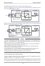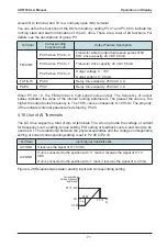
Operation
and
Display
VDF730
User
Manual
-
56
-
Function Code
Parameter
Name
Setting
Range
Default
P7
-
14
LED
display
stop
parameters
1
–
511
7
6
5
4
3
2
1
0
Set
frequency
(
Hz
)
Bus
voltage
(
V
)
DI
state
DO
state
AI1 voltage
(
V
)
AI2 voltage
(
V
)
Counted value
Length
value
15 14 13 12 11
10
9
8
Pulse frequency
(
Hz
)
Reserved
51
When
the AC drive is powered
on
again
after
power
failure
,
the
parameters
that
are
selected
before
power
failure
are
displayed
.
Select
the
required
parameters
by
pressing
.
The
following
example
shows
how
to
set
P7
-
13
to
display
the
running
parameters
on
LED
.
1
)
Assume
that
the
following
parameters
need
to
be
displayed
:
Running frequency
,
bus voltage
,
output voltage
,
output current
,
output power
,
and PID
feedback
2
)
Set
the
corresponding
bit
of
each
parameter
to
be
displayed
to
1
.
3
)
Convert
the
binary
data
to
a
decimal
value
,
and
set
this
value
in
P7
-
13
.
7
6
5
4
3
2
1
0
Low bits
15 14
13
12 11
10
9
8
High bits
0
0
1
1
1
1
0
1
0
0
1
0
0
0
0
0
2
0
3
D
Binary
Hexadecimal
P7
-
13
Decimal
2 x 16³
+
0 x 16²
+
3 x 16
+
13
=
8253
4
.
4
Starting
or
Stopping
the
AC
Drive
4
.
4
.
1
Selecting
the
Start
/
Stop
Command
Source
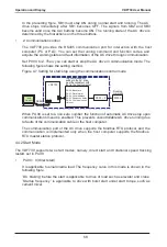
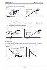
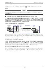
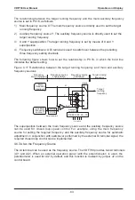
There are three start
/
stop command sources
,
namely
,
operation panel control
,
terminal
control
,
and
communication
control
.
You
can
select
the
command
source
in
P0
-
00
.
Function
Code
Parameter
Name
Setting
Range
Description
Default
P0
-
00
Command
source
selection
0
:
Operation
panel
control
(
indicator
OFF
)
1
:
Terminal
control
(
indicator
ON
)
2
:
Communication
control
(
indicator
blinking
)
Press
RUN
or
STOP
RES
to start or
stop
the
AC
drive
.
A
DI
terminal
needs
to
be
defned
as
the
run
/
stop
terminal
.
The
Modbus
-
RTU
communication
protocol
is
used
.
0
Summary of Contents for VDF730 Series
Page 1: ...VDF730 Series...
Page 7: ......
Page 8: ...1 Safety Information and Precautions...
Page 15: ...Safety Information and Precautions VDF730 User Manual 14...
Page 16: ...2 Product Information...
Page 30: ...3 Mechanical and Electrical Installation...
Page 51: ...Mechanical and Electrical Installation VDF730 User Manual 50...
Page 52: ...4 Operation and Display...
Page 75: ...Operation and Display VDF730 User Manual 74...
Page 76: ...5 Function Code Table...
Page 97: ...Function Code Table VDF730 User Manual 96...
Page 98: ...6 Description of Function Codes...
Page 153: ...Description of Function Codes VDF730 User Manual 152...
Page 154: ...7 EMC...
Page 158: ...8 Troubleshooting...


