Operation
and
Display
VDF730
User
Manual
-
64
-
The
following
fgures
show
how
to
use
the
AI
as
the
frequency
source
.
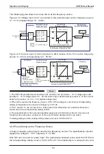
Figure 4
-
18 Voltage input of AI1
connected
to
the potentiometer as the
frequency
source
(
2
–
10
V
corresponding
to
10
–
40
Hz
)
P2
-
08
=
2
.
00 V
P2
-
09
=
20
.
0
%
P2
-
10
=
10
.
00 V
P2
-
11
=
0
P2
-
12
=
80
.
0
%
P2
-
13
=
0
.
1s
P0
-
01
=
1
Running
frequency
Terminal
Function
code
(
default value
)
10V
AI1
.
GND
Frequency
source
selection
P0
-
18
=
0
Analog setting
Frequency
feature
setting
P2
-
08 to
P2
-
13
:
relationship between
AI1 setting and corresponding value
1
2
3
0
-
10 VDC
Potentiometer
2 k
Ω
Default
:
0
.
02
-
10
V corresponding to
0
-
50Hz
AI
Corresponding
setting
80
.
0
60
.
0
40
.
0
20
.
0
0
.
00
2
.
00
4
.
00
6
.
00 8
.
00 10
.
00
P2
-
08
P2
-
09
P2
-
12
P2
-
10
2
-
10Vcorresponding to10
-
40Hz
P0
-
04
=
50
.
00 Hz
0
.
0
Unit
:
V
Unit
: %
Figure 4
-
19 Current input of AI2 connected to 4DA module of the PLC as the frequency
source
(
4
–
20
mA
corresponding
to
0
–
50
Hz
)
P0
-
01
=
2
Running
frequency
Terminal
Function code
(
default
value
)
Frequency
source
selection
P0
-
18
=
0
Frequency
feature setting
P2
-
14 to
P2
-
19
:
relationship between A2
I
setting and corresponding value
Default
:
0
-
10V corresponding
to0
-
50Hz
P2
-
14
=
4
.
0
P2
-
15
=
0
.
0
%
P2
-
16
=
20
.
0
P2
-
17
=
0
P2
-
18
=
100
%
P2
-
19
=
0
.
1s
AI
20
.
0
P2
-
14
P2
-
15
P2
-
18
4
-
20 mA
corresponding to0
-
50Hz
P0
-
04
=
50
.
00Hz
16
.
0
12
.
0
8
.
0
4
.
0
100
.
0
P2
-
18
0
80
.
0
60
.
0
40
.
0
20
.
0
0
.
0
Corresponding
setting
Unit
:
mA
Unit
: %
V
I
Selection by
jumper J1
AI2
GND
Selection by
jumper
J1
I
:
AI2current
input
V
:
AI2voltage input
Note
:
Select
the analog input
mode based on the output
mode
of the D
/
A module
.
A
4
-
20 mA
Note
1
.
The
VDF730
provides
two
AI
terminals
(
AI1
and
AI2
).
AI1
provides
0
–
10
V
voltage
input
.
AI2
provides
0
–
10
V
voltage
input
or
0
–
20
mA
current
input
,
determined
by
jumper
J1
on
the
control
board
.
AI3
provides
-
10
V
to
+
10
V
bipolar
voltage
input
.
2
.
When
AI
is
used
as
the
frequency
source
,
100
%
of
the
voltage
or
current
input
corresponding
setting
corresponds
to
the
maximum
frequency
in
P0
-
04
.
3
.
P2
-
11
and
P2
-
17
can
not
be
set
to
1
at
the
same
time
.
Otherwise
,
AI1
and
AI2
will
become
invalid
due
to
the
corresponding
setting
confict
.
4
.
The
potentiometer
of
the
external
operation
panel
and
AI2
terminal
on
the
AC
drive
can
not
function
at
the
same
time
.
Jumper
J2
on
the
control
board
decides
which
one
works
.
5
.
Analog
setting
and
the
corresponding
values
are
set
in
P2
-
08
to
P2
-
19
.
4
.
6
.
4
Pulse
Setting
as
the
Frequency
Source
In
many
scenarios
,
pulse
input
is
used
as
the
frequency
source
.
The
specifcations
of
pulse
signals
are
:
voltage
9
–
30
V
,
frequency
0
–
50
kHz
.
Only
DI5
can be
used
for pulse
input
.
The relationship between
pulse
input
from DI5
and
the
corresponding
setting
is
set
in
P2
-
20
to
P2
-
25
.
The
relationship
is
a
two
-
point
line
,
and
Summary of Contents for VDF730 Series
Page 1: ...VDF730 Series...
Page 7: ......
Page 8: ...1 Safety Information and Precautions...
Page 15: ...Safety Information and Precautions VDF730 User Manual 14...
Page 16: ...2 Product Information...
Page 30: ...3 Mechanical and Electrical Installation...
Page 51: ...Mechanical and Electrical Installation VDF730 User Manual 50...
Page 52: ...4 Operation and Display...
Page 75: ...Operation and Display VDF730 User Manual 74...
Page 76: ...5 Function Code Table...
Page 97: ...Function Code Table VDF730 User Manual 96...
Page 98: ...6 Description of Function Codes...
Page 153: ...Description of Function Codes VDF730 User Manual 152...
Page 154: ...7 EMC...
Page 158: ...8 Troubleshooting...


