


LAYOUT AND FUNCTION
19
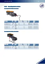
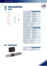
Feed terminals
The infeed can be realized as an end feed via the transfer guides or on the line as a line feed.
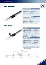
Transfer guides
Transfer guides are the contact-protected ends of the conductor rails at the end of the lines and mechanical
line interruptions (switches, lifting stations, etc.). Transfer guides are available with or without feed capability.
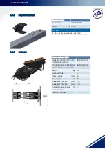
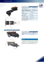
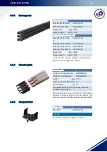
Current collectors
The current collectors are manufactured from impact-resistant plastic and stainless steel parts. The current is
drawn via a carbon brush. The length of the current collector connection cable may not exceed 3 m if the down-
stream overcurrent protection device is not designed to handle the capacity of the connection cable. Refer also
to DIN VDE 0100, part 430 and DIN EN 60204-32. (Note: this is often the fact if more than one current collec-
tor is used in the system). The cross section of the supplied connecting cables is designed for the stated nom-
inal currents. The reduction factors according to DIN VDE 0298-4 must be observed for the various laying
procedures. According to DIN EN 60204-1 and DIN EN 60204-32, the continuity of the ground conductor sys-
tem via wiper contacts must be ensured using suitable measures. As a simple and suitable measure, it is rec-
ommended to double the PE current collector.
Further remarks
• (VCL2-50/40A) - The fixpoint may only be installed in the system 1x. Normally the end of the conductor
system is fixed at the location of the feed terminal. The end cap/transfer guide on the other end may not
be fixed. If both ends need to be fixed because of the system, an expansion section is required.
(100 A variant) - Here the power is not fed in via the transfer guides, rather only via line feed.
• Rail holder spacing according to chapter: „5.3.1 “.
• Connectors cannot be removed again, therefore align and install them carefully.
• (Shuttle applications without VMT profile) - The connector caps must rest on the installation surface to pre-
vent any incorrect deflection or warping of the conductor system.
• The shortest permissible rail segment is 300 mm.
Summary of Contents for VCL Series
Page 95: ...INDEX 93 U Unloading 88...
Page 96: ...CE Technical Documentation...