background image


MALFUNCTIONS

81


6

MALFUNCTIONS

6.1

Safety information about malfunctions

WARNING!

Risk of injury in case of improper troubleshooting!

Improper troubleshooting may cause serious injuries or property damage.

Ensure sufficient installation space before beginning any work.

Switch off power supply, verify that the system is free of voltage, and secure
against switching back on.

6.2

Conduct in case of malfunction

General principle:

• If case of malfunctions that present an immediate hazard to persons or property, immediately activate the

safety devices.

• Determine the cause of the fault.
• Notify the person in charge at the place of operation.

NOTICE!

The inspection and maintenance tasks listed in the technical documentation must be
performed and documented regularly:

(location, spare part, task performed, date, name of inspector).

Only persons with the required training, qualification and authorization may per-
form troubleshooting work on the system.

Summary of Contents for VCL Series

Page 1: ...TRANSLATION OF THE ORIGINAL GERMAN OPERATING INSTRUCTIONS VCL COMPACT CONDUCTOR SYSTEM INSTALLATION MANUAL SYSTEM MANUAL MAINTENANCE MANUAL EN V 1 01...

Page 2: ...pment 11 2 7 Safety devices 12 2 8 Conduct in case of danger or accident 12 2 9 Signage 13 3 Technical data 14 3 1 VCL2 14 3 2 VCL3 16 3 3 VMT 17 4 Layout and function 18 4 1 System description VCL2 V...

Page 3: ...ning 47 5 2 1 Operation 47 5 2 2 Decommissioning 47 5 3 Installation VCL2 VCL3 48 5 3 1 Assembly preparation 48 5 3 2 Determining the system lengths 52 5 3 3 End segment with feed terminal fixpoint 54...

Page 4: ...7 2 Wear parts 84 7 3 Conductor system maintenance 85 7 4 Current collector maintenance 86 7 5 Cleaning 87 8 Transport and storage 88 8 1 Safety instructions for transport and storage 88 8 2 Transpor...

Page 5: ...ersonnel in the immediate vicinity The basic requirement for safe working is compliance with all specified safety instructions and instructions This documentation does not give instructions for operat...

Page 6: ...icity that will result in death or serious injury unless avoided The actions to prevent the hazard are identified here WARNING The source of the hazard is described here This combination of a symbol a...

Page 7: ...n of the manufacturer except for internal purposes 1 4 Disclaimer The information in this document has been compiled in consideration of applicable standards and regulations accepted rules of engineer...

Page 8: ...product require the permission of the man ufacturer Genuine spare parts and manufacturer approved accessories provide safe ty The use of non approved parts voids any liability of the manufacturer Alw...

Page 9: ...ductor rail is only to be used for indoor installations It can be mounted hanging or laterally Appropriate use includes following all the information in these instructions Any use beyond or other than...

Page 10: ...ches control units pressure and sensing devices safety parts circuity breakers that have been used to unlock a system part or that can be used to connect electricity If this is not possible then the c...

Page 11: ...rds that may arise from the special operating conditions at the instal lation site These must be implemented as facility instructions for the operation of the system Over the entire time the owner has...

Page 12: ...ask Electrically qualified person see VDE 0105 100 Due to their professional training knowledge experience and knowledge of the relevant standards and regu lations professional electricians are able t...

Page 13: ...ainst flying particles and liquid sprays Helmet Helmets protect against falling or flying parts and materials Gloves Gloves protect hands against chafing and abrasion cuts and punctures as well as aga...

Page 14: ...egulations the following safety instructions must be observed The following accident prevention regulations UVV Germany respectively the new Accident Prevention Reg ulations Principles of Prevention D...

Page 15: ...that the components are not live or in tension unauthorized approxima tion WARNING Danger from illegible signs Over time labels and signs can get dirty or can become unreadable in other ways which me...

Page 16: ...2 x phase 1 x phase PE Cross section connection cable mm 6 16 Conductor material Copper CU or steel F Protection class IP2X Dielectric strength according to DIN 53481 kV mm 22 4 Volume resistivity acc...

Page 17: ...collectors Y axis mm 20 Operating conditions Operating temperature C 30 to 55 Max humidity at ambient temperature 10 C to 40 C 98 non condensing Max deviation of operating temperature K 50 Flammabilit...

Page 18: ...e 2 x phase PE Cross section connection cable mm 16 Conductor material Copper CU or steel F Protection class IP2X Dielectric strength according to DIN 53481 kV mm 22 4 Volume resistivity according to...

Page 19: ...nditions Operating temperature C 30 to 55 Max humidity at ambient temperature 10 C to 40 C 98 non condensing Max deviation of operating temperature K 50 Flammability insulator profile flame retardant...

Page 20: ...C or 60 volts DC The VDE finger shows that it cannot touch live parts The insulation rail covering the conductor rail offers good insulation for maximum safety Several wiper lines can be combined with...

Page 21: ...the stated nom inal currents The reduction factors according to DIN VDE 0298 4 must be observed for the various laying procedures According to DIN EN 60204 1 and DIN EN 60204 32 the continuity of the...

Page 22: ...LAYOUT AND FUNCTION 20 4 2 System overview VCL2 VCL3 System overview VCL2 2 pin 1 End segment 2 Conductor system 3 Transfer guide with without fixpoint 4 Hanger 5 Connector material 1 2 3 4 5...

Page 23: ...LAYOUT AND FUNCTION 21 System overview VCL3 3 pin 1 End segment 2 Conductor system 3 Transfer guide with without fixpoint 4 Hanger 5 Connector material 1 2 3 4 5...

Page 24: ...rted For exposed connectors strictly adhere to the spacing of 150 mm Arrangement example 2 Fixed end segment sliding end segment 1 Fixed end segment 2 Conductor system 3 Conductor system 4 Sliding end...

Page 25: ...2 40F 4000SSD 0281544 00 Weight 100C kg 2 406 Weight 40F kg 2 190 Delivery length mm 4000 Hanger spacing mm 800 Segment Section Phase PE VCL2 100C 1000HSC 0281531 00 VCL2 100C 2000HSC 0281532 00 VCL2...

Page 26: ...gers on request EndsegmentPhase VCL2 100C SSD 0281510 00 VCL2 40F SSD 0281516 00 Weight kg 0 324 Delivery length mm 1000 Segment Section Phase PE VCL2 100C HSC R 0281515 00 VCL2 100C HSC L 0281518 00...

Page 27: ...A 50 Expansion section Phase PE DT DVCL2 100C HSC 0281507 00 DT DVCL2 40F HSC 0281509 00 Weight kg 0 324 Delivery length mm 1000 Max current A 50 Line feed Phase ES VCL2 100C SSD 50A 0281502 00 ES VCL...

Page 28: ...kg 0 020 Current collector DEAS SA DEAS 2 30 2 SS 2 5 0 2 2 PA for control current 2823983 00 0 SA_DEAS 2 30 2 HS 2 5 0 2 2 PA for main power with PE 2823998 00 0 Weight kg 0 4 Number of poles 2 Phase...

Page 29: ...for main current with PE 2823997 00 0 Current collector EASL SA EASL 20 2 SS 0 2 PA V E for control current 2823982 00 0 SA EASL 20 2 HS 0 2 2 PA V E for main current with PE 2823997 00 0 Weight kg 0...

Page 30: ...5PH 6 3 Phase Black 2 5 4 5 2809171 00 2809173 00 AL FLA2 5PE 6 3 PE Green yellow 2 5 3 9 2809175 00 2809177 00 AL FLA4PH 6 3 Phase Black 4 5 3 2823085 00 2823085 00 3 AL FLA4PE 6 3 PE Green yellow 4...

Page 31: ...no 1 m ID no 5 m Al RKLA2 5PH M5 Phase Black 2 5 4 5 2808971 00 2808971 00 5 Al RKLA2 5PE M5 PE Green yellow 2 5 3 9 2808958 00 2808958 00 5 Al RKLA4PH M5 HL Phase Black 4 5 3 2821809 00 2821809 00 5...

Page 32: ...0 5 Al RKLA4PH M6 HL Phase Black 4 5 3 2808751 00 2808751 00 5 Al RKLA4PE M6 PE Green yellow 4 4 9 2808752 00 2808752 00 5 Al RKLA6PH M6 Phase Black 6 6 5 2808745 00 2808745 00 5 Al RKLA6PE M6 HL PE G...

Page 33: ...0171817 00 Weight kg 0 142 Delivery without profile Equipotential bonding from VCL profile to VMT pro file Rail section with PE grounding VCL2 40F 1000HSCP 0281547 00 VCL2 100C 1000HSCP 0281548 00 Eq...

Page 34: ...4000SSD 0281604 00 Weight 100C 4m kg 3 522 Weight 40F 4m kg 3 300 Delivery length mm 4000 Hanger spacing mm 800 Segment Section Phase PE VCL3 100C 4000HSC 0281594 00 VCL3 100C 3000HSC 0281593 00 VCL3...

Page 35: ...End segment Phase ESM VCL3 100C SSD 0281578 00 ESM VCL3 40F SSD 0281585 00 Weight 1m kg 0 662 Delivery length mm 1000 Segment Section Phase PE ESM VCL3 100C HSC R 0281579 00 ESM VCL3 100C HSC L 028158...

Page 36: ...A 50 Expansion section Phase PE DT DVCL3 100C HSC 0281600 00 DT DVCL3 40F HSC 0281606 00 Weight kg 0 953 Delivery length mm 1000 Max current A 50 Line feed Phase ES VCL2 100C SSD 50A 0281502 00 ES VCL...

Page 37: ...ight kg 0 020 Current collector DEAS SA DEAS 2 30 2 SS 3 5 0 2 2 PA for controller 0281610 00 SA_DEAS 2 30 2 HS 3 5 0 2 2 PA for main power with PE 0281615 00 Weight kg 0 4 Number of poles 3 Phase spa...

Page 38: ...E for control current 0281616 00 SA EASL 20 3 HS 0 2 2 PA V E for main current with PE 0281617 00 Weight kg 0 12 Number of poles 3 Phase spacing mm 15 Max current A 20 Tolerance X direction mm 15 Tol...

Page 39: ...with VMT PASK current collector Ident No SA PASK 50 3L HS 3 4 0281633 00 SA PASK 50 3R HS 3 4 0281634 00 SA PASK 50 4L HS 4 4 0281624 00 SA PASK 50 4R HS 4 4 0281627 00 SA PASK 50 5L HS 5 6 0281625 00...

Page 40: ...5PH 6 3 Phase Black 2 5 4 5 2809171 00 2809173 00 AL FLA2 5PE 6 3 PE Green yellow 2 5 3 9 2809175 00 2809177 00 AL FLA4PH 6 3 Phase Black 4 5 3 2823085 00 2823085 00 3 AL FLA4PE 6 3 PE Green yellow 4...

Page 41: ...6PE M4 PE Green yellow 6 6 3 2808738 00 2808738 00 3 RKLA for M5 type Pin Color Cable cross section mm2 Outer diam eter mm ID no 1 m ID no 5 m Al RKLA2 5PH M5 Phase Black 2 5 4 5 2808971 00 2808971 00...

Page 42: ...0 5 Al RKLA4PH M6 HL Phase Black 4 5 3 2808751 00 2808751 00 5 Al RKLA4PE M6 PE Green yellow 4 4 9 2808752 00 2808752 00 5 Al RKLA6PH M6 Phase Black 6 6 5 2808745 00 2808745 00 5 Al RKLA6PE M6 HL PE G...

Page 43: ...0171817 00 Weight kg 0 142 Delivery without profile Equipotential bonding from VCL profile to VMT pro file Rail section with PE grounding VCL3 40F 1000HSCP 0281638 00 VCL3 100C 1000HSCP 0281637 00 Eq...

Page 44: ...f other applications e g in crane technology Displacement and positioning systems can of course also be used in parallel A further plus for the user are the large hanger dis tances which enable quick...

Page 45: ...ixpoint Profile VMT 6000 0171546 01 Weight kg 12 336 Delivery length mm 6000 Terminal connector KV VMT 0171536 00 Weight kg 0 845 Compact holder Weight kg Ident No KH VCL4 VMT 0 385 0171818 00 KH VCL5...

Page 46: ...sole for auxiliary sup port HST 15 1 062 0171539 00 3 VMT S Screw console 15 0 902 0171547 00 4 VMT 55 125 Clamping console 15 55 to 65 65 to 75 75 to 85 85 to 95 95 to 105 105 to 115 115 to 125 1 600...

Page 47: ...HSE 450 450 0781694 00 HRL HSE 500 500 0781677 00 Type Height mm Ident No HRL HST 50 250 250 0157172 00 HRL HST 50 300 300 0152804 00 HRL HST 50 350 350 0156393 00 HRL HST 50 400 400 0152661 00 HRL H...

Page 48: ...nauthorized persons who do not meet the requirements described here do not know the dangers in the respective work area Keep unauthorized persons away from the work area If in doubt speak to people an...

Page 49: ...ctly observed during assembly Appropriate handling of materials Clean and metallic bright surfaces on all contact points Smooth crossovers free of burrs of the conductor rail profiles at the ends in o...

Page 50: ...uctor rail adjustable torque wrench for 1 4 Nm 5 Nm 7 Nm and 15 Nm reversible ratchet with an extension and nut with SW 7 200 mm steel rule Allen wrench size 4 soft face hammer head about 50 mm dia Sc...

Page 51: ...kplace Required tools Drill 4 5 mm Assembly instructions 1 Determine position for the bore hole and fix in position 2 Drill hole with 4 5 mm dia Drill out mounting holes for holder Arrangement example...

Page 52: ...ment without fixpoint Assembly instructions Requirements Clean and tidy workplace Required tools Drill bit according to table below 4 6 mm 4 9 mm Assembly instructions 1 Determine position for the bor...

Page 53: ...Drilling template for VCL in VMT Ident No 0171840 00 Weight kg 0 109 Assembly safety device Ident No 0281526 Weight kg 0 050 Mounting handle for feed terminal VCL MZ MH ES VCL 10027863 Weight kg 0 09...

Page 54: ...14 File FSF Ident No 2812964 Weight kg 0 085 Component Length mm Conductor system segment 4000 End segment start 1000 End segment end 1000 Component Length mm Line feed 1000 Expansion joint 1000 Possi...

Page 55: ...5 26 106018 90 2 26 27 110019 60 2 27 28 114020 30 2 28 29 118021 00 2 29 30 122021 70 2 30 31 126022 40 2 31 32 130023 10 2 32 33 134023 80 2 33 34 138024 50 2 34 35 142025 20 2 35 36 146025 90 2 36...

Page 56: ...nt the hangers to the carrier using suitable expanding rivets 2 Use the plastic hammer for fixing Step 3 Assembly instructions 1 Connect the screw terminal with the feed cable DANGER Danger of life du...

Page 57: ...a risk of crushing of the ex tremities between the individual components Take care of your extremities Wear personal protective equipment see Chap ter 2 Step 6 Assembly instructions 1 Mount the end s...

Page 58: ...amp to relieve the fixpoint during connector installation 5 3 4 Transfer guides NOTICE One of the two transfer guides must be mounted as a fixpoint The transfer guides may only have an air gap of betw...

Page 59: ...il joint with the mounting handle and a plastic ham mer CAUTION The connector is not reusable If assembly is unsuc cessful or the connection is faulty please proceed as described in Chapter 5 3 6 Step...

Page 60: ...hed the penul timate 4 meter section Determine the exact length to the end point and adapt the last sections accordingly 5 3 6 Renewing conductor rail joints Assembly disassembly steps Cutting tool De...

Page 61: ...the connectors and connecting cap on the last section 2 Clip the end segment into the hanger and connect the section 3 Insert the screw terminals in both conductor rail ends and push the transfer guid...

Page 62: ...Clean and tidy workplace Required tools Tape measure Handsaw chop saw File Assembly steps 1 Pull the copper profile out of the insulating housing for exactly 15 mm and make sure that the copper is fl...

Page 63: ...x 4 N per carbon brush The current collector must be able to move freely Connecting cables may not restrict or impede movement Double current collector assembly DEAS Assembly instructions Prerequisite...

Page 64: ...sys tem phase center off NOTICE Installation dimension 80 mm Number of poles 3 6 Phase spacing 15 mm Max current 50 A Tolerance X direction 15 mm Tolerance Y direction 20 mm Contact pressure approx 4...

Page 65: ...trans fer guide In special cases a fixpoint can also be realized using a hanger On the back of the conductor line each hanger has two recesses for fixing CAUTION This type of fixpoint may only be use...

Page 66: ...th help of the drilling device drill through the insulating housing and the back of the conductor line 3 Press the fixpoint clamps into the previously drilled holes and align them with the recesses of...

Page 67: ...Requirements Clean and tidy workplace Assembly steps 1 Before installing the expansion joint in the line press the mounting clip into the expansion gap 2 Mount the expansion joint in the intended line...

Page 68: ...r in tension unauthorized approxima tion CAUTION Danger of crushing between the individual components During assembly there is a risk of crushing of the extremities between the individual components T...

Page 69: ...tep 2 Assembly instructions 1 Pull the two conductor system parts apart and re move the connection terminals Step 3 Assembly instructions 1 Connect the connection terminals to the screw terminals At t...

Page 70: ...m behind over a joint connector 2 Now screw the hexagon socket screws to the cor responding connection terminal with 7 Nm transfer guide M5 feed terminal M6 The mounting handle prevents twisting durin...

Page 71: ...g 2 570 Installation pliers Ident No 0171533 00 Weight kg 0 700 Drilling template for fixpoint terminal MZ BS AH VCL2 0281525 MZ BS AH VCL3 0281608 Weight kg 0 050 Drilling template for VCL in VMT MZ...

Page 72: ...15 0 882 0171839 00 2 VMT SPW Clamping console for auxiliary sup port HST 15 1 062 0171539 00 3 VMT S Screw console 15 0 902 0171547 00 4 VMT 55 125 Clamping console 15 55 to 65 65 to 75 75 to 85 85 t...

Page 73: ...aces of less than 2 meters the alternate fixing of the hangers is not required NOTICE Please observe the following torques regarding the different hangers The AV VMT BS hangers are fixated with drill...

Page 74: ...cted type Tighten the M10 screws to a torque of 15 Nm Ensure that the clamping springs always face upwards For other clamping springs please use the torques specified in the table above Step 2 Assembl...

Page 75: ...pment see Chap ter 2 Step 4 Assembly instructions 1 Attach the connection sections and lock them us ing the installation pliers as shown in Step 3 NOTICE Install the VMT sections with a max air gap of...

Page 76: ...VMT shorter lengths Step 6 Required tools Sawing device SV VMT Assembly instructions 1 If required you can create shorter lengths on the construction side using the SV VMT sawing de vice 2 Deburr the...

Page 77: ...tor is essential See IEC 60364 4 41 Step 1 Required tools Wrench Assembly instructions 1 Screw the equipotential bonding cable 4 3 12 Equipotential bonding or 4 4 12 as shown to a point on the VMT pro...

Page 78: ...TION Danger of crushing between the individual components During assembly there is a risk of crushing of the extremities between the individual components Take care of your extremities Wear personal p...

Page 79: ...the exact position of the feed terminal on the supplied system plan The feed terminal must have a distance of 200 mm from the hanger on the side to which the connecting cables are led away 2 Make two...

Page 80: ...d dimension 100 mm NOTICE Observe the hanger distances from the supplied sys tem or installation plan Step 2 Required tools Assembly safety device Assembly instructions 1 Click the first section into...

Page 81: ...e sure that the lugs of the holders are properly snapped in place see figure below 2 For other transfer guides proceed as described in step 2 NOTICE The profile connectors should be mounted outside th...

Page 82: ...parts or situations after assembly and issue and sign an acceptance certificate Check the general functionality of the system Clearances of the line transitions and transfers Open spaces and interfer...

Page 83: ...on 6 2 Conduct in case of malfunction General principle If case of malfunctions that present an immediate hazard to persons or property immediately activate the safety devices Determine the cause of t...

Page 84: ...ing instructions must be observed DANGER Danger of life due to electrical current Contact with live parts can result in life threating injuries Make sure that the components are not live or in tension...

Page 85: ...sons cannot assess the risks involved in operating the sys tem and expose themselves and others to the risk of serious or fatal injuries Have all work performed only by persons qualified for the task...

Page 86: ...placement head 0 5 0 016 2808580 00 SK EK DEAS 2 30 PE 36 6 3 H Rear replacement head 0 5 0 016 2808581 00 SK EK DEAS 2 30 PH 36 6 3 V Front replacement head 0 5 0 016 2808575 00 SK EK DEAS 2 30 PE 36...

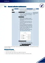
Page 87: ...ductor rails and of burn marks Replace damaged burnt parts In particular remove accumulated car bon brush dust at separating points and transfer guides using a hand brush Remove any small burns or di...

Page 88: ...joints bearings and hinge pins Inspection for mechanical damage of any type Electrical checks Check for wear of graphite contacts firm seat of all contact screws and cable attachments Clean oxidized...

Page 89: ...lass H filter Retrofitting a HEPA filter is required Do not eat drink or smoke during work Dust in the vacuum cleaner bag or the air filter can be disposed of as commercial waste in the usual quantiti...

Page 90: ...sport damage upon receipt If any external damage is found Refuse delivery or accept delivery only conditionally Note the scope of the damage in the transport documents or on the carrier s delivery not...

Page 91: ...WARNING Risk of death from improper replacement or removal Errors during the removal or replacement of components may cause life threatening situations or significant property damage Observe the safe...

Page 92: ...CTRIFICATION SYSTEMS VCL2 Series VCL3 Series Have been investigated by UL in accordance with the Standard s indicated on this Certificate Standard s for Safety UL508 CSA C22 2 NO 14 18 Industrial Cont...

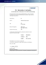
Page 93: ...cified hereafter conform to the relevant EU regulations This declaration will be void when amendments not approved by us will be made to the products Compact coonductor system Paul Vahle GmbH Co KG Po...

Page 94: ...ls 19 G Grounding and short circuiting 8 H Hangers 18 I Information to the instructions 3 Isolation 9 M measuring equipment 48 O Operating company 9 Operation 47 Owner obligations 9 Q Qualifications 1...

Page 95: ...INDEX 93 U Unloading 88...

Page 96: ...CE Technical Documentation...

Reviews: