


MAIN
CIRCUIT
Service Manual M4 - M10
29.12.1999
Page
72
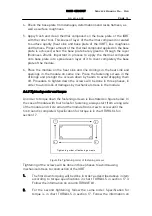
column TORQUE #2.
3.
The third and final tightening, again the order as above in phases 1. and
2. The specification for torque is in chart TORQ.XLS in section 17.
Follow the information on column TORQUE FINAL.
8.4.6 Spare parts
IGBTs
Detailed information for the spare parts is available from spare parts lists in
section “SPARE PART LIST”.
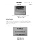
8.5 Balancing thick foil resistors
8.5.1 Description
Balancing resistors are thick foil resistors on aluminium oxide basis in plate
shape which can stand high voltage and high energy pulse for a short time.
8.5.2 Operation
Balancing resistors balance voltages over the series connected electrolytic
DC bus capacitors and discharge dangerous voltages within reasonable time
when power supply is switched off.
8.5.3 Troubleshooting
Damaged resistor can normally be inspected visually due in case of
overloading the resistors are mechanically broken. Resistance values also
can be checked by multimeter. Refer the measured values to the
corresponding values mentioned in spare part lists.
8.5.4 Assembly instructions
Check installation surface of the heat sink, from dents, bursts, unflatness and
possible damages, which may affect unadvantageously for thermal junction
from resistor to the heat sink.
8.5.5 wiring table
Check the connections for balancing resistors from main circuit diagrams
chapter 8.9.
8.5.6 Spare parts
Refer spare part list in section 14.


