


TROUBLESHOOTING
Service Manual M4 - M10
11.07.2002
Page
58
With power board CB00042 or CB00055 remove also SCR gate connector X19!
With new power board (CB00055 M10 400/500V and CB00042 M8 to M10 690V)
layout it is possible to disconnect DC+ from main circuit by pulling jumper X22
off and connect external power supply to “AMP” connector X21. Remove
always jumper from each power board. With this power board it is not
required to disconnect X8 or X19!
Proceed with the procedure as above to check voltages at terminals (X3-13)
on the Control board. If the voltages are correct, but value on monitoring page
n7 is incorrect, failure is located on the Control board and it shall be replaced
as instructed in section 9.3.7.
If the results from the measurements are not correct, continue trouble
shooting by checking voltages from each Extender boards from the terminal
(X3-13). If voltages are correct, replace Extender boards one by one according
to instructions in section 9.6.9, until failed one has located. If the voltages
measured from the Extender board are out of tolerances, pull out pin(s) X3-13
and measure signals from connector X15-13 on the Power board(s), board by
board. If voltage level variates from values above (3.58V, 3.70V. 3.58V) at
connector, particular Power board is defective and has to be replaced
according to instructions in section 9.2.7. Otherwise failure can be suspected
to be on one of the Extender board in unit.
7.3.2.5 Checking of braking chopper
Check parameter 4.5 to enable brake chopper function (p4.5=1).
Visual checking:
At the first, look at power modules, connections and junctions for visible
damages. Cracked enclosure of the IGBT is relatively common sign of a
destructive failure in main circuit and due to failure mechanism is easy to
identify. Cracked case of power component is easy to find if exist, however to
find and identify reason for the failure needs more than visible inspection.
If IGBT bridge after the visible checking cannot be judged to be as failed,
advanced techniques have to be used.
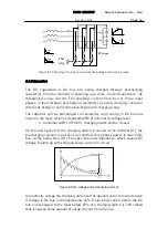
For measurements of the IGBT in dynamic braking chopper, external braking
resistor will be disconnected. Condition of free wheeling diode will be checked
by measuring threshold voltage cross PN junction of the diode.
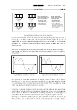
The checking can be conducted by biasing the PN junction at the first in
forward, when the threshold voltage shall be about 0,5V and infinite when
checking with reversed biasing.
Measurement can be performed from terminals of the braking resistor.


