TROUBLESHOOTING
Service Manual M4 - M10
11.07.2002
Page
54
between all modules. Keep same polarity when measuring, reading might be
different. If measuring without gate cables, reading is lower.
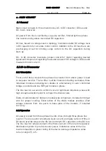
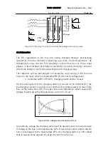
Principle of the measurement on the drawing below.
Cgate
Cgate
Cgate
To IGBT
To IGBT
Wire harness (Power board - IGBT)
Measurement of gate capacitance in GE-junction.
Figure 7.1 Measurement of gate capacitance
7.3.2.3 Checking of gate drivers
PREPARING DRIVE TO CHECKING:
Powering up only the power board(s), and DC bus (DC link capacitors) is not
powered:
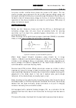
At connector X3 on the Control board, pins (2-4), (8-10) and (14-16) will be
connected together to bypass feedback signal from the IGBTs. This has to be
done to avoid fault F4 at start up and to be able to measure gate signals while
control circuitry is operating only. With frame sizes M4 to M7, use extended
connector between control board and power board (pins are too short to add
jumper).
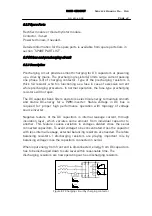
2 4 8 10
14
16
Pin to pin connections at connector X3
X3
1
13
26
2-4
8-10
11
14-16
2
Figure 7.2 Pin to Pin connection at connector X3
To eliminate activation of input phase supervision circuitry, pin 11 at
connector X3 on the Control board has to be pulled out about 10mm from the
connector. Remove option board temporarily if installed.


