


MAIN
CIRCUIT
Service Manual M4 - M10
29.12.1999
Page
66
only two screws by following same instructions. Specifications for torques are
in pages of the table TORQ.XLS in section 17.
2.
1.
3.
4.
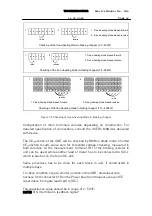
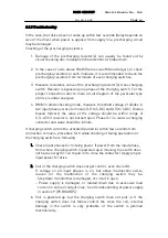
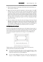
Tigh te nin g orde r of fa stening screw s
Figure 8.6 Tightening order of fastening screws
Tightening of the screws will be done in three phases to avoid causing
mechanical stress to construction of the module.
1.
The first down torquing will be done in order as described above in item
according to torque specifications in table TORQ.XLS in section 17.
Follow the information on column TORQUE #1.
2.
For the second tightening, follow the same order. Specification for
torque is in table TORQ.XLS in section 17. Follow the information on
column TORQUE #2.
3.
The third and final tightening, again in the order as above in phases 1.
and 2. The specification for torque is in table TORQ.XLS in section 17.
Follow the column TORQUE FINAL.
8.2.6 Wiring table
Wiring of front end is following next order of connections:
Terminal (L1) =>Line reactor => Rectifier (L1)
Terminal (L2) => Line reactor =>
Contactor or directly to rectifier => Rectifier (L2)
Terminal (L3) => Line reactor =>
Contactor or directly to rectifier => Rectifier (L3)
Rectifier (L1) => Power board (X8-3)
Rectifier (L2) => Power board (X8-5)
Rectifier (L3) => Power board (X8-7)
Rectifier (+) => Capacitor (+) C1, (C3)
Rectifier (-) => Capacitor (-) C2, (C4)
Above order of connections is valid with possible exemptions. For this reason,
always refer to main circuit diagram for particular drive and mark up cables
and wires for identification before disconnection.


