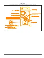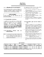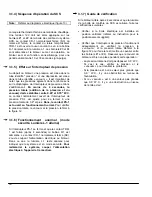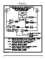
5
7. 48 inches Long of extruded grey gasket 1/8’’ X
1/2’’;
8. A 90
o
galvanized increaser 3 inches / 4 inches
elbow for the burner combustion air intake junction
with 4 inches aluminum pipe;
9. 4 inches diameter collar for aluminum combustion
air pipe and 90
o
elbow joint;
10. Half moon cover;
11. Half moon plate to fix the vent pipe on the vent
terminal assembly;
12. Plate "L";
13. 1 inches thick neoprene outside gasket;
14. One tube or high temperature sealant;
2.4)
VENT TERMINAL INSTALLATION
CAUTION
Do not forget to remove the 4 inches diameter pipe
from the 5 inches diameter pipe. The appliance can
not operate with both pipes inside each other. This
configuration is used for shipping purposes only.
2.4.1) Preparation and requirements
The vent terminal can be installed to accommodate
six different vent and combustion air pipe
combinations as shown on figure 3. Find a location on
an outside wall that respects all conditions stated in
part 2, section 2. An opening of 7.75” x 7.75” should
be provided in the wall for the vent terminal
installation.
2.4.2) Orientation of the flexible
connection
The vent terminal is factory assembled with the vent
pipe and is ready for use if your application calls for
position # 1 or position # 4 as shown on figure 3. If the
position required for the application is position # 1 or #
4, go directly to section 2.4.3 of this chapter. If the
position required for the application is one of # 2, # 3,
# 5 or # 6 you should proceed using the following
instructions.
To meet a Horizontal Side connection for either
combustion air pipe or vent pipe you should
rotate the square tube 90
o
CW or CCW depending
of your needs.
1. Take the outdoor flanged guard off in removing
the 8 stainless steel metal screws as identified “A”
(see figure 4);
2. Take the venturi assembly off in removing the 8
stainless steel metal screws as identified “B” (see
figure 4);
Note:
1- The cone diffuser and vent pipe assembly
stay together during this operation.
2- The slope direction of the outdoor end cone
diffuser should be down when the vent
terminal is installed.
3. Turn the square tubing on is position required;
4. Screw the venturi assembly (see note 2) on the
square tubing;
5. Screw the outdoor flange guard to the square
tubing section of the vent terminal and make sure
that the square opening of the guard is aligned
with the outdoor end cone diffuser.
Summary of Contents for SCS-5-08-3
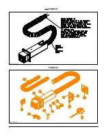
Page 5: ...6 FIGURE 1 FIGURE 2 DNS 0701 Rév B DNS 0501 Rév D ...
Page 6: ...7 VUE DE CÔTÉ FIGURE 3 DNS 0866 Rév A VUE ARRIÈRE ...
Page 12: ...13 FIGURE 11 POSITIONNEMENT DES TUBES CHAUDIÈRE AVEC SERPENTIN À GAUCHE DNS 0689 Rév C ...
Page 13: ...14 FIGURE 12 POSITIONNEMENT DES TUBES CHAUDIÈRE AVEC SERPENTIN À DROITE DNS 0690 Rév C ...
Page 16: ...17 FIGURE 13 Diagramme électrique DNS 0463 Rév C ...
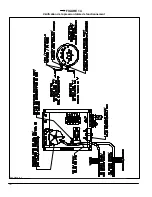
Page 17: ...18 FIGURE 14 Vérification de la pression totale de fonctionnement DNS 0499 Rév C ...
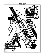
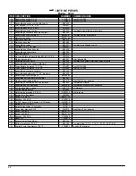
Page 20: ...21 LISTE DE PIÈCES Modèle SCS 5 DNS 0475 Rév I ...
Page 26: ...6 FIGURE 1 FIGURE 2 DNS 0701 Rev B DNS 0501 Rev D ...
Page 27: ...7 FIGURE 3 SIDE VIEW REAR VIEW DNS 0866 Rev A ...
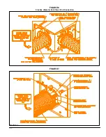
Page 30: ...10 FIGURE 6 5 inches diameter Vent Pipe End Connection FIGURE 7 DNS 0481 Rev B DNS 0867 Rev A ...
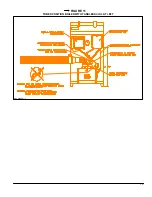
Page 33: ...13 FIGURE 11 TUBES POSITION BOILER WITH TANKLESS COIL AT LEFT DNS 0689 Rev C ...
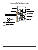
Page 34: ...14 FIGURE 12 TUBES POSITION BOILER WITH TANKLESS COIL AT RIGHT DNS 0690 Rev C ...
Page 37: ...17 FIGURE 13 Electric wiring diagram DNS 0643 Rev C ...
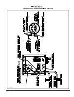
Page 38: ...18 FIGURE 14 Verification of the total operating pressure DNS 0499 Rév C ...


