


11
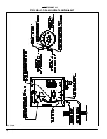
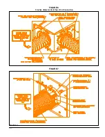
FIGURE 8
2.6)
BURNER
SLEEVE
WITH
PRESSURE
TAP
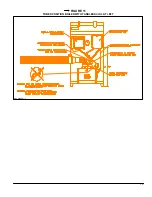
The SCS system is equipped with a safety control
device. A burner sleeve with pressure tap figure 9 will
be used for the over fire pressure reading. The burner
sleeve should be installed with the pressure tapping
on top as shown on figure 9. The Riello 40-BF5 burner
should be installed on the burner sleeve with insertion
length of 3 ½ inches.
2.7)
CONNECTION TO THE BURNER
COMBUSTION AIR INTAKE
1. Install the 90
o
galvanized elbow supplied with the
kit on the 3 inches diameter burner air intake.
Secure in place with a ¾” long metal screws;
2. Insert the 4 inches combustion air pipe to the 4
inches end of the elbow;
3. Install all around the joint, the extruded grey
gasket;
4. Install the 4 inches collar supply around the
aluminum 4 inches diameter pipe and centered
with the elbow joint;
5. Tighten the collar firmly on the assembly.
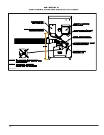
2.8)
ELECTRIC
BOX
CONNECTIONS
1. The electric box supplied with this kit encloses
pressure switch and
should be installed
vertically to
respect the calibration of the
pressure switch;
2. The position for a practical installation and a
proper operation is shown on the figure 11 and on
the figure 12;
3. Install the ‘’VACUUM’’ silicone hose on the top
right side 5/8” diameter opening of the Riello 40-
BF5 Oil Burner with the compress fitting supplied
with the kit. Refer to the figures 11 and 12 for
correct position of the tubing;
IMPORTANT
1/8 silicone hoses must be install to allow the flow of
the water from control to the burner and the burner
sleeve. They must be cut at the good length, if
necessary.
4. Install the ‘’PRESSURE’’ silicone hose on the
pressure tap fitting of the burner sleeve previously
installed between the burner flange and the boiler.
Refer to the figures 11 and 12 for the correct
position of the tubing;
5. Refer to the electric wiring diagram shown on
figure 13 for electrical connection. The installation
of the equipment should be in accordance with the
regulations of authorities having jurisdiction.
DNS-0868 Rev. A
Summary of Contents for SCS-5-08-3
Page 5: ...6 FIGURE 1 FIGURE 2 DNS 0701 Rév B DNS 0501 Rév D ...
Page 6: ...7 VUE DE CÔTÉ FIGURE 3 DNS 0866 Rév A VUE ARRIÈRE ...
Page 12: ...13 FIGURE 11 POSITIONNEMENT DES TUBES CHAUDIÈRE AVEC SERPENTIN À GAUCHE DNS 0689 Rév C ...
Page 13: ...14 FIGURE 12 POSITIONNEMENT DES TUBES CHAUDIÈRE AVEC SERPENTIN À DROITE DNS 0690 Rév C ...
Page 16: ...17 FIGURE 13 Diagramme électrique DNS 0463 Rév C ...
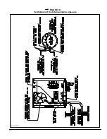
Page 17: ...18 FIGURE 14 Vérification de la pression totale de fonctionnement DNS 0499 Rév C ...
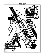
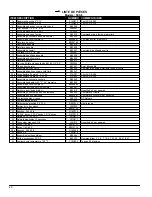
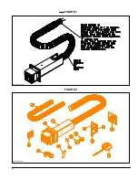
Page 20: ...21 LISTE DE PIÈCES Modèle SCS 5 DNS 0475 Rév I ...
Page 26: ...6 FIGURE 1 FIGURE 2 DNS 0701 Rev B DNS 0501 Rev D ...
Page 27: ...7 FIGURE 3 SIDE VIEW REAR VIEW DNS 0866 Rev A ...
Page 30: ...10 FIGURE 6 5 inches diameter Vent Pipe End Connection FIGURE 7 DNS 0481 Rev B DNS 0867 Rev A ...
Page 33: ...13 FIGURE 11 TUBES POSITION BOILER WITH TANKLESS COIL AT LEFT DNS 0689 Rev C ...
Page 34: ...14 FIGURE 12 TUBES POSITION BOILER WITH TANKLESS COIL AT RIGHT DNS 0690 Rev C ...
Page 37: ...17 FIGURE 13 Electric wiring diagram DNS 0643 Rev C ...
Page 38: ...18 FIGURE 14 Verification of the total operating pressure DNS 0499 Rév C ...