PARTS LIST
Model : SCS-5
22
ITEM DESCRIPTION
NUMBER
COMMENTS
1a
Chimney liner 5" X 8'
Z13G012
For SCS-5-08-3
1b
Chimney liner 5" X 20'
Z13G009
For SCS-5-20-3
2
Hot half cover ass'y
B02046
3
Extruded joint 1/2" X 1/8" X 25'
J06L001
4
Hex nut M14-1.5 black
F07F025
5
Smoke plug ass'y
A00334
Smoke plug & gasket included
6
Complete outlet cover ass'y
B02032
7
Complete collar ass'y 5"
B02048-01
Collar & gasket included
8
Collar gasket
B02027-02
9
Outlet half side
B02018
10
Outlet gasket
B02009
11
Venturi ass'y
B02057
12
Lag screw 1/4" X 3 1/2" zinc
F04J001
13
Exterior screen ass'y
B02036
14
Wall box ass'y
B02035
15
Wall gasket
B02010
16
Type #a screw hex head slotted #8-18 X 3/4" SS
F03F024
17
Seal plate joint
B02897
Stainless steel
18
Square tube ass'y
B02058
With short & long interior guide
19
Cold half cover ass'y
B02047
20a
Flexible pipe 2 walls 4" X 11' AL
Z13I007
For SCS-5-08-3
20b
Flexible pipe 2 walls 4" X 23' AL
Z13I006
For SCS-5-20-3
21
Central cover ass'y
B02045
22
Adaptor 90
o
3" X 4" diameter ass'y
B02049
23
Complete 4" collar ass'y
B02048-03
24
Complete burner flange ass'y
B02041
25
Burner flange gasket
B00419
Quantity of 2 per appliance
26
Electrical box cover ass'y
B02044
Complete with label
27
Electrical box ass'y
B02039-01
Complete with cover and controls
28
Electrical wire white / red
A00373
RC Network
29
Amber indicating light
L01L003
30
Pressure switch 0.8
R99F022
31
Screw terminal strip 4 positions
L05F004
32
Tube 3/16" SIL70
B30157-12
33
Plug .204 X 3/4
G14F010
34
Tee 3/16" hose X 3/16" hose X 3/16" hose
G07Z015
35
Relay SPDT 120VAC
L01H011
36
4 seconds time-delay relay
L01H017
37
Liquid tight bushing PG 9
L04I012
Quantity of 3 per appliance
38
Tube 1/8 SIL60
B30157-11
39
Tube 1/4 SEL65
B30157-14
39a
Plug .246 X 3/4
G14F009
40
Bushing 5/8"
L04G014
41
Burner electrical kit
B00964
42
Accessories box
B02059
With item 2, 3, 6, 7, 19, 21, 22, 23, 24, 27 & 43
43
High temperature sealant 700
o
F
F10G005
85 g per tube
Summary of Contents for SCS-5-08-3
Page 5: ...6 FIGURE 1 FIGURE 2 DNS 0701 Rév B DNS 0501 Rév D ...
Page 6: ...7 VUE DE CÔTÉ FIGURE 3 DNS 0866 Rév A VUE ARRIÈRE ...
Page 12: ...13 FIGURE 11 POSITIONNEMENT DES TUBES CHAUDIÈRE AVEC SERPENTIN À GAUCHE DNS 0689 Rév C ...
Page 13: ...14 FIGURE 12 POSITIONNEMENT DES TUBES CHAUDIÈRE AVEC SERPENTIN À DROITE DNS 0690 Rév C ...
Page 16: ...17 FIGURE 13 Diagramme électrique DNS 0463 Rév C ...
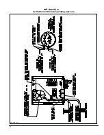
Page 17: ...18 FIGURE 14 Vérification de la pression totale de fonctionnement DNS 0499 Rév C ...
Page 20: ...21 LISTE DE PIÈCES Modèle SCS 5 DNS 0475 Rév I ...
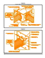
Page 26: ...6 FIGURE 1 FIGURE 2 DNS 0701 Rev B DNS 0501 Rev D ...
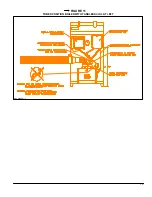
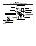
Page 27: ...7 FIGURE 3 SIDE VIEW REAR VIEW DNS 0866 Rev A ...
Page 30: ...10 FIGURE 6 5 inches diameter Vent Pipe End Connection FIGURE 7 DNS 0481 Rev B DNS 0867 Rev A ...
Page 33: ...13 FIGURE 11 TUBES POSITION BOILER WITH TANKLESS COIL AT LEFT DNS 0689 Rev C ...
Page 34: ...14 FIGURE 12 TUBES POSITION BOILER WITH TANKLESS COIL AT RIGHT DNS 0690 Rev C ...
Page 37: ...17 FIGURE 13 Electric wiring diagram DNS 0643 Rev C ...
Page 38: ...18 FIGURE 14 Verification of the total operating pressure DNS 0499 Rév C ...


