


4
PART 2
INSTALLATION
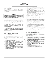
2.1)
GENERAL
These instructions are intended for qualified
technicians who have been trained to install this type
of equipment.
CAUTION
Installation of this equipment by an unqualified person
may lead to equipment damages and/or hazardous
conditions which may lead to bodily harm.
All local and national code requirements as the CSA:
B139-M91 and the CSA-C22.1 governing the
installation of oil burning equipment, wiring and vent
connections must be followed.
The SCS system should not be installed on
incinerators, condensing type appliances or solid fuel
burning appliances.
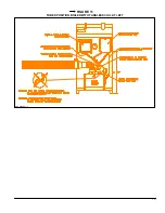
The vent terminal unit may be installed through a
combustible or non-combustible wall with a maximum
thickness of 22 inches. The minimum wall thickness is
2 inches.
2.2)
GENERAL INSTALLATION
GUIDELINES
The first step in installing the SCS system is to find
the location that is in accordance with the following
criterias.
A vent should not terminate :
a. Directly above a paved sidewalk or paved
driveway, which is located between two buildings ,
and that serves both buildings;
b. Less than 2.13 meters (7 feet) above any paved
driveway or paved sidewalk;
c. Within 1.8 meters (6 feet) of window, door, or a
mechanical air supply inlet to any building
including soffit opening;
d. Above a gas meter/regular assembly within 1
meter (3 feet) horizontally of the vertical center-
line of the regulator;
e. Within 1.8 meters (6 feet) of any gas service
regulator vent outlet or 1 meter (3 feet) of an oil
tank vent or oil tankfill inlet;
f. Not less than 0.3 meter (1 foot) above grade level;
g. Within 1.8 meters (6 feet) from another
combustion appliance air intake;
h. Within 1.8 meters (6 feet) of property line;
i.
Underneath a veranda, porch or deck;
j.
So that the flue gases are directed at combustible
material or any openings of surrounding buildings
that are within 1.8 meters (6 feet);
k. Less than 1 meter (3 feet) from an inside corner of
an "L" shaped structure;
l.
The bottom of the vent termination opening is less
than 0.3 meter (1 feet) above any surface that
may support snow, ice or debris;
m. So that the flue gases are directed toward
brickwork, siding, or other construction, in such a
manner that may cause damage from heat or
condensation from flue gases.
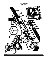
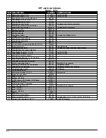
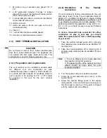
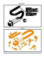
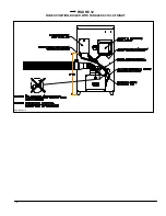
2.3)
LIST OF COMPONENTS
Please consult figure 2. The parts being shipped with
the SCS system are :
1. A vent terminal assembly with the 8 or 20 feet of 5
inches diameter stainless steel pipe;
2. A electrical box with pressure switch, timer and
relay factory wired and mounted;
3. A 11 feet or 23 feet of 4 inches diameter
aluminum combustion air flexible pipe;
4. A 5 inches diameter Breech plate with test
opening port;
5. A 5 inches diameter collar with gasket;
6. A Burner Flange Adapter with pressure tap;
Summary of Contents for SCS-5-08-3
Page 5: ...6 FIGURE 1 FIGURE 2 DNS 0701 Rév B DNS 0501 Rév D ...
Page 6: ...7 VUE DE CÔTÉ FIGURE 3 DNS 0866 Rév A VUE ARRIÈRE ...
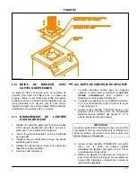
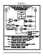
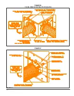
Page 12: ...13 FIGURE 11 POSITIONNEMENT DES TUBES CHAUDIÈRE AVEC SERPENTIN À GAUCHE DNS 0689 Rév C ...
Page 13: ...14 FIGURE 12 POSITIONNEMENT DES TUBES CHAUDIÈRE AVEC SERPENTIN À DROITE DNS 0690 Rév C ...
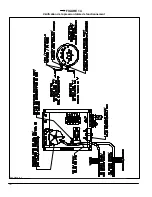
Page 16: ...17 FIGURE 13 Diagramme électrique DNS 0463 Rév C ...
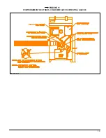
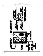
Page 17: ...18 FIGURE 14 Vérification de la pression totale de fonctionnement DNS 0499 Rév C ...
Page 20: ...21 LISTE DE PIÈCES Modèle SCS 5 DNS 0475 Rév I ...
Page 26: ...6 FIGURE 1 FIGURE 2 DNS 0701 Rev B DNS 0501 Rev D ...
Page 27: ...7 FIGURE 3 SIDE VIEW REAR VIEW DNS 0866 Rev A ...
Page 30: ...10 FIGURE 6 5 inches diameter Vent Pipe End Connection FIGURE 7 DNS 0481 Rev B DNS 0867 Rev A ...
Page 33: ...13 FIGURE 11 TUBES POSITION BOILER WITH TANKLESS COIL AT LEFT DNS 0689 Rev C ...
Page 34: ...14 FIGURE 12 TUBES POSITION BOILER WITH TANKLESS COIL AT RIGHT DNS 0690 Rev C ...
Page 37: ...17 FIGURE 13 Electric wiring diagram DNS 0643 Rev C ...
Page 38: ...18 FIGURE 14 Verification of the total operating pressure DNS 0499 Rév C ...