background image


17


1.


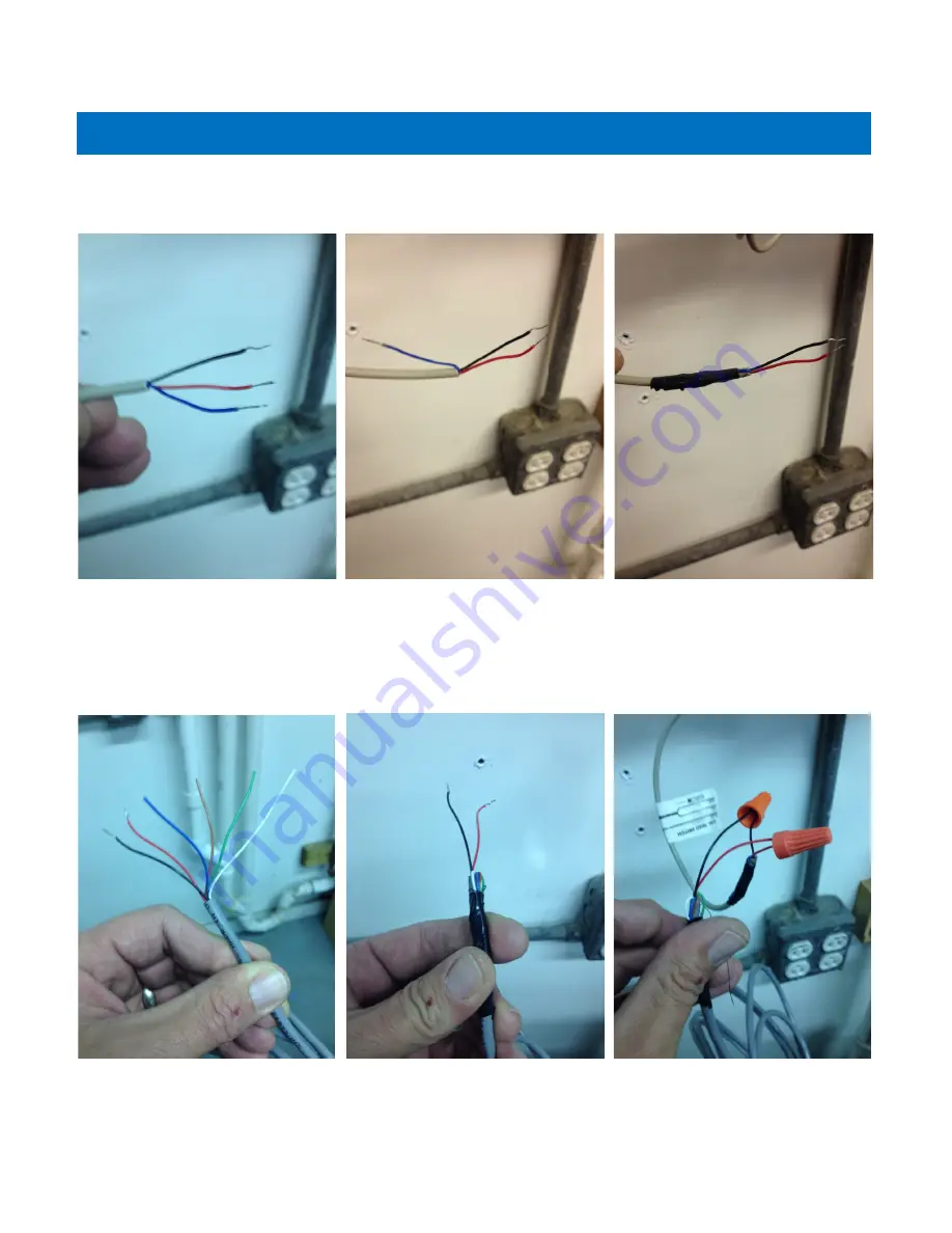
The wire coming from the previously installed water meter should have three wires.  

A black, red and blue wire.  The blue wire is not used and should be folded back and 

taped to prevent it from making contact with anything.  


2.


The wire coming from the chemical injection pump will have several colors.  Fold 

back all wires but the red and black wire.  Make sure the wires that are folded back 

are not touching each other or anything else.  Tape the wires back.  Now connect the 

black wires together with a wire nut or butt splice connector.  Connect the two red 

wires using a wire nut or butt splice connector.  There is no voltage on these wires.  

An enclosure can be used or the wires connections can simply be taped to insulate 

the wires if desired. 


Chemical Pump Wiring Installation Instructions


Summary of Contents for Matrixx inFusion 081-IF Series

Page 1: ...ION 1 5 10 31 14 Owners Manual Models 081 IF XXX US Water Systems Corporate Office 1209 Country Club Road Indianapolis IN 46234 info uswatersystems com www uswatersystems com 1 800 608 8792 Visit us o...

Page 2: ...hedule 30 Limited Lifetime Warranty 31 Safety Guide Be sure to check the entire system for any shipping damage or parts loss Also note damage to the shipping cartons Contact US Water Systems at 1 800...

Page 3: ...scard all unused parts and packaging material after installation Small parts remaining after the installation could be a choke hazard The Matrixx inFusion system provides iron and sulfur removal throu...

Page 4: ...stems guarantees 100 iron and sulfur removal with its Matrixx InFusion System which utilizes Hydrogen Peroxide or H2O2 Hydrogen peroxide or H2O2 is a powerful yet versatile oxidant that is both safe a...

Page 5: ...on and sulfur precipitating it from solution This reaction is immediate When these contaminants are oxidized with hydrogen peroxide H2O2 the extra oxygen molecule oxidizes the contaminants and the by...

Page 6: ...ovide for the installation of a by pass valve if unit is not equipped with one The Catalytic Carbon is equipped with a bypass valve CAUTION Water pressure is not to exceed 80 psi water temperature is...

Page 7: ...n turning the basket clockwise to lock it in place Place the upper basket over the distributor tube and push the valve on the tank Thread the valve on the tank by turning it clockwise Be sure not to c...

Page 8: ...ion nipple apply Teflon tape and install it in the inlet plumbing Do not over tighten the plastic nipple or damage could occur 3 Install the rubber washer gasket in the connecting nut and install the...

Page 9: ...o no over tighten the nipple in the outlet plumbing connection or damage could occur 5 Install the rubber washer gasket in the nut and tighten the outlet plumbing to the water me ter outlet connection...

Page 10: ...joints being soldered near the valve must be done before connecting any piping to the valve Always leave at least 6 152 mm between the control valve and joints being soldered when soldering pipes that...

Page 11: ...ed of larger diameter than the drain line This linear pipe should have a physical drop toward the drain 1 2 10 The goal is to have a gravity drain without much back pressure when traveling long distan...

Page 12: ...lasts up to 25 minutes During this time water can be heard running intermittently to the drain New Sounds Automatic Hard Water Bypass During Regeneration In the case of emergency the system can be iso...

Page 13: ...pump mounting bracket on the solution tank Center the bracket on the back side of the tank Install the two longer screws supplied in the outer holes Tighten all screws Chemical Solution Tank with Pump...

Page 14: ...pump on the bracket that was installed on the tank us ing the screws taped to the bracket 3 Drill a 1 4 hole in the top of the solution tank and install the tubing into the tank Chemical Solution Tank...

Page 15: ...other end of the tank suction tube to the chemical injection pump inlet The inlet is identified by an arrow point toward the pump Be sure the sleeve is in stalled on the tubing properly The beveled s...

Page 16: ...en the nut The outlet is identified by and arrow that is point ing away from the pump 7 Install the other end of the chemical pump outlet tubing to the previously installed in jection check valve Be s...

Page 17: ...colors Fold back all wires but the red and black wire Make sure the wires that are folded back are not touching each other or anything else Tape the wires back Now connect the black wires together wi...

Page 18: ...The pump is now programmed See the Bubble Method for pump adjustment 5 Once the pump is programmed pour the supplied Hydrogen Peroxide in the chemical tank Now push and hold the prime button until the...

Page 19: ...lay reads 0000 Regeneration cycle will initiate at the next designated regeneration time 2 To start Immediate Extra Cycle First complete above step With Gallons Remaining Until Next Regeneration at 00...

Page 20: ...d the next menu item will flash 4 To set the Number of Days between Backwash Cycles A press the Set Changebutton Repeat instructions from step 2 Notes 1 Maximum value is 29 2 If value set to 0 Automat...

Page 21: ...Logix Bluetooth app 1 Go to the App store on the phone to be used and search for Water Logix 2 Download the free Water Logix app 3 Open the app to begin programing 4 Once the app is open it will begin...

Page 22: ...rrent time of the device 2 Backwash Frequency Tap on the Filter Backwash Frequency box and input the de sired days between backwashing Most applications will set this to 3 days If iron or sul fur is e...

Page 23: ...on the orange font then use the keyboard that appears to change the value 4 Backwash This should be set to 10 mins and should not be changed 5 Rest This should be set to 2 mins and should not be chan...

Page 24: ...reset 1 Total Regenerations This parameter shows how many times the system has regenerat ed since it was put in service or since the last time the value was reset 2 Total Water Treated This parameter...

Page 25: ...neration Initiation There are two options for regenerating the system Tap on the desired option and press OK Regenerate Now Regenerate Now will que an immediate regeneration and will start instantly R...

Page 26: ...the unit Allow all air to escape from the unit before turning the water on fully then allow water to run to drain for the entire backwash cycle or until all media fines are washed out of the filter in...

Page 27: ...container 20 30 defined air bubbles in the center of the solution in the glass that come to the top of the water level and dissipate immediately This should be the optimal H2O2 injection setting The...

Page 28: ...ring this step After power is restored the Signature 2 will return and finish the cycle where it left off prior to the power interruption When used without battery back up during a power failure the u...

Page 29: ...econds it is an indication that the system is being overfed with H2O2 This occurs because after installation the water will become cleaner after the plumbing system has been flushed and the initial do...

Page 30: ...ill Check Valve Replace injection check valve as need ed 1 5 Years H2O2 Solution Tank Periodically check the solution level and refill as needed Varies by water usage Matrixx Tank Check the clock and...

Page 31: ...Sediment Filter Housings or Chemical Solution Tanks damaged due to environmental issues or improper installation are not covered GENERAL PROVISIONS This warranty does not apply to any commercial or i...

Reviews: