background image

31

DS1723-024

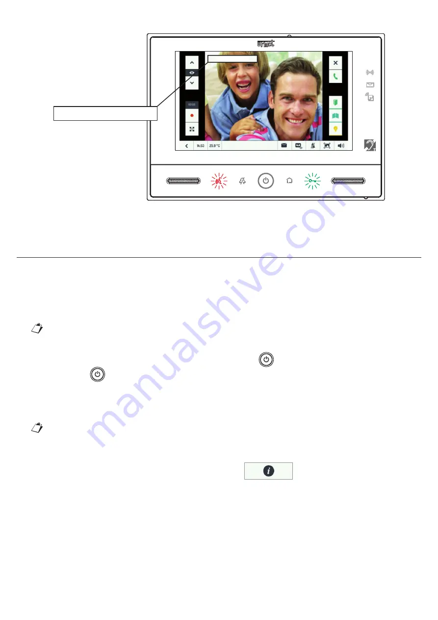
The following appears on the video door phones in the home and in the of

fi

 ce:

PANEL 1: #1

PANEL 1: #1

All the call related functions will be available in standard con

fi

 guration. See the VIDEO DOOR PHONE CALL TEST 

section. 

UPDATING THE VIDEO DOOR PHONE SOFTWARE


Proceed as follows to update the software (SW) of the device:
1. Go 

to 

Download\Software\Technical software\Communication 1723/71\-/72 video door phone Kit


www.urmet.com site after having signed up (free registration);

2. Download 

the 

update 

fi

 le 

1723_vX.Y.Z-W_fup.zip

 and copy it to the root directory of your microSD card;


   The 

fi

 le name 

vX.Y.Z-W

 indicates the SW version. 

3.  Insert the card into the video door phone;
4.  Switch on the display, if it is off, by pressing the central button 

,

5. Hold 

the 

button   pressed until the video door phone reboots.

6.  Wait for the update to end (the operation may take as long as 5 minutes);
7.  Success of the operation is con

fi

 rmed by the presence of a green stripe on the video door phone screen 

and after a few seconds by a subsequent restarting of the device.


  If red stripe appears on the video door phone, repeat the procedure from step 5 because the    


update was not successful. The video door phone will continue to operate with the previous    

 software 

version.

8.  When the video door phone is active again, open the page 

 to check verify that the software 

version which appears on the screen has the same code as that shown in the name of the 

fi

 le on the 

microSD card.

9.  Finally, remove the card. The update procedure is done.

Summary of Contents for Note 2 1723 Series

Page 1: ...DS 1723 024 LBT 20469 Mod 1723 ONE AND TWO HOUSEHOLD KIT WITH PANEL AND COLOUR 7 HANDS FREE MONITOR Ref 1723 71 1723 72 CONFIGURATION BOOKLET IP45 IK07 IP45 IK07...

Page 2: ...F THE THERMOSTAT TO THE BOILER 17 WIRED CONNECTION OF THE THERMOSTAT TO THE BOILER 17 ENDING CONFIGURATION 18 OFFICE WITH ATTACHED HOME SETTING 19 AUTOMATIC DOOR OPENER SETTING 20 TEST 22 VIDEO DOOR P...

Page 3: ...he clock icon in the bottom right to open the following window 1 When entering date and time always clear the contents of the field FIRST and THEN enter the new required value Tap on the required fiel...

Page 4: ...a weak one provides a minimum level of protection from actions that the end user could change unintentionally WARNING After having entered the password the Installer menu can be accessed even multiple...

Page 5: ...art of the gate by pressing and open the second only by pressing In this case Check that dip switch 5 is in the OFF position default Connect the terminals SE and SE timed capacitive discharge to a dec...

Page 6: ...hen controlling the camera Finally tap on the icon on the top right you can assign specific names to the various controlled cameras The set names will appear superimposed on the image during the contr...

Page 7: ...t the buttons to the devices The last item can be used to reset radio access points BUTTON CONFIGURATION Select this item to open the complete page of all available buttons regardless of their future...

Page 8: ...uttons it consists of in sequence As in other kits by tapping on a composite button you can set The name of the button The list of Yokis buttons which are part of the composition The delay in the sequ...

Page 9: ...useful to make only the configured home automation buttons i e only those which generate an action visible to the final user The installer can therefore access to the specific configuration item in ho...

Page 10: ...g page Tap on the icon you want to associate with the Stairs Light button 4 If you want to delete an association tap on the highlighted icon so that no icons are selected IMPORTING YOKIS BUTTONS FROM...

Page 11: ...l the access points of all buttons of the video door phone Run M 24 SETTING THE ALARM FUNCTION The alarm function can be set to Detect the opening of a door e g the front door Detect the energising of...

Page 12: ...sed during the exit time Entrance time with the alarm armed the energising of the sensor will generate an alarm only after the entrance time To which devices to send an alarm signal Enabling the alarm...

Page 13: ...camera to use 9 for recording the video clip can be defined The encoding to use is 1 door panel camera 2 second panel camera if present 3 4 5 6 cameras connected to the CCTV interface Ref 1723 69 The...

Page 14: ...tacts can be modified In the Configuration menu which can be opened using the icon on the top right select the Installer menu type in the password 1937 and select Relay Contacts and select one of the...

Page 15: ...owing diagram Power supply 230 Vac Relay REL1C MTR2000ERP X receiver E2BPP X transmitter LETTER BOX APT0 10 m Panel Brown Brown Brown Purple White White Green WARNING THE USE OF THE REL1C RELAY IS MAN...

Page 16: ...ply 230 Vac Rel REL1C MTR2000ERP X receiver E2BPP X transmitter E4BPP X transmitter LETTER BOX APT0 LETTER BOX APT1 10 m Panel Brown Brown Brown Purple Purple Grey White White White Green A single E4B...

Page 17: ...ESS CONNECTION OF THE THERMOSTAT TO THE BOILER Position Yokis MTR2000ERP relay near the boiler Choose two home automation buttons which will be used exclusively for controlling the relay connected to...

Page 18: ...f the thermostat to the boiler can be defined as follows IF Contact 2 was assigned to the Thermostat function then Contact 2 will automatically appear on this line and there will be nothing to do the...

Page 19: ...ly from home or no Importantly the kit provides the possibility of controlling two doors in different manner and so button can be programmed to open the office door by doing so you can use the automat...

Page 20: ...ration menu In the Configuration menu which can be opened using the icon on the top right select the Installer menu type in the password 1937 tap on the arrow button on the bottom and then select Auto...

Page 21: ...21 DS1723 024 Remove the tick from the Auto Door Opening option In this way the button will no longer be visible on the Home Page...

Page 22: ...o be easily located the button When the door opens the icon will light up on the panel It is also possible to switch on the stairs or garden light using button or to open the garage door using the but...

Page 23: ...will appear using the last chosen video format To cycle the other cameras in the system using the side arrows You must return to the camera of the panel to answer To record a video clip of the visito...

Page 24: ...door phone by tapping on the screen or the button Tap on the camera control button The video door phone will show the image from the panel camera also providing the possibility to open the door or sta...

Page 25: ...right flashes during the possible output time any alarms during Exit Time will have no effect and turns green fixed to its end to indicate successful activation The video door phone display will switc...

Page 26: ...isarmed during the entry time 16 by tapping on the icon to clear the tick HOW TO BROWSE VIDEO CLIPS All recorded video clips automatically in case of alarm or voice mail or manually in case of recordi...

Page 27: ...orded by additional camera The video clip name always comprises the number of the camera which recorded it 1 to 6 the name of the camera customisable during installation the date the time suffix _AL i...

Page 28: ...using the middle button and insert a microSD card 18 Switch the video door phone back on and first tap the icon and then the Alarms tab A list of the most recent detected alarms will appear with the i...

Page 29: ...n from the letterbox by opening the rear collection door and check that the LED goes out WARNING If you want to repeat the test on the same letterbox wait for 10 seconds after closing of the rear coll...

Page 30: ...he call was sent The following appears on the video door phones in the home and in the office PANEL 1 0 PANEL 1 0 All the call related functions will be available in standard configuration See the VID...

Page 31: ...o the video door phone 4 Switch on the display if it is off by pressing the central button 5 Hold the button pressed until the video door phone reboots 6 Wait for the update to end the operation may t...

Page 32: ...nd the electric lock is not activated KEY MEMORISATION PROCEDURE Only keys memorised can activate the electric lock connected to the call station To memorise the keys 1 Move the master key close to th...

Page 33: ...he call station 2 The call station emits a confirmation beep 3 Hold the Master key in front of icon for at least 5 seconds 4 The call station emits a long confirmation beep Remove the key immediately...

Page 34: ...is buttons During this step you will need to press the Connect button on several receivers Each Yokis button can be configured to control a single activation module or multiple modules Scenario or Cen...

Page 35: ...35 DS1723 024 Select Configure Buttons to go to the following page The Yokis buttons are the first 8 on top Tap on the Yokis button you want to configure Five items will appear...

Page 36: ...figuration presses The green LED on the video door phone corresponds to the red LED of a Yokis remote control the notification flashes can be seen on it The expected number of flashes is shown on the...

Page 37: ...Access Point E7 R1 This is useful for controlling a specific remote receiver or also more than one positioned on Bus Radio For more information see E Range Extension with Radio Bus and E 1 Definition...

Page 38: ...Mode for controlling up to four receivers On a video door phone instead is often useful to use the buttons in centralised mode e g to have a button which closes all the shutters another one which turn...

Page 39: ...is advisable to select the Off Up Stop function see previous paragraph switch off the lights and closing the shutters Not Home scenario If you wish to perform various functions at the same time such...

Page 40: ...he mode to timer mode and wait for 7 flashes on the receiver Send 26 E 26 to configure the time in minutes and wait for 6 flashes on the receiver Send 14 E14 to set the timer to 15 minutes and wait fo...

Page 41: ...Yokis buttons on the video door phone but not their labels On the Home Page of the video door phone press the Configuration icon select the Installer button enter the password 1937 and then select the...

Page 42: ...t this point you can Import the NAME of the button the one that the user will see by tapping on the displayed menu item Check correct operation of the button by pressing the Test button It is not poss...

Page 43: ...o control the centralised locking of all the shutters Close All in Radio Bus mode and a second Yokis button to switch on the lights in the living room and kitchen Living Room and Kitchen Lights On in...

Page 44: ...ollowing page The composite buttons are characterised by the default name COMP BTN N and are located in the third and fourth row the two on the left There are six in total Tap on the composite button...

Page 45: ...ose desired at least 2 Delay Between Buttons The following page will appear Here you can choose a waiting time between the functions of the single buttons forming the composite For example if the comp...

Page 46: ...46 DS1723 024 The order with which the selected buttons will be activated in sequence from the first to the last or from the last to the first...

Page 47: ...47 DS1723 024...

Page 48: ...T 20469 Area tecnica servizio clienti 39 011 23 39 810 http www urmet com e mail info urmet com MADE IN CHINA URMET S p A 10154 TORINO ITALY VIA BOLOGNA 188 C Telef 39 011 24 00 000 RIC AUT Fax 39 011...

Reviews: