Maintenance
Section
4-15
AB38 Work Platform
3.
Place the bearing spring into the bearing bore.
4.
Take a complete armature assembly, including
bearings, and insert commutator end bearing
into the bearing bore.
Note:
Do not reuse bearings which have been
removed from armature shaft. Keep assembly
in a vertical position. Use extreme care not to
damage armature with bearing pullers. New
bearings should be installed by pressing inner
race of bearing onto proper position on
armature shaft.
5.
Set the brushes to final position and lock with
springs.
6.
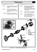
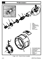
Place the complete stator down over the
vertical armature, and into position on the
commutator cover.
7.
The stator assembly must be placed in a
definite relationship with the commutator covers
in order to obtain a neutral brush setting. There
is a match-mark on both items. These two
marks must line up exactly.
Rotate until they do.
8.
Assemble the pulley end cover in the proper
relationship. Insert mounting bolts and tighten
alternately to ensure a good mechanical
alignment.
9.
Spin the shaft by hand to see if it is free. Be
sure motor leads (if used) are not touching
together. If the leads are touching, a generator
action will give the effect of friction in the motor.
A no-load test can now be performed. At rated
voltage, observe the no-load current. It should
be less than 20% of the nameplate full load
current. Anything higher will indicate:
• Brushes are not on neutral setting
(check matchmarks for exact alignment)
• Faulty armature.
NOTE:
Following assembly, the electric motor
may turn in the wrong direction. The cause
of this will be that the brush holder assembly
has been connected the wrong way. To solve
this disassemble and reconnect in the
proper way. Reversing the polarity will not
solve this problem as this is a series wound
motor.
MAINTENANCE INTERVALS &
PROCEDURES
Every
500
working hours, or annually
Brushes -
Check the wear, the correct seating,
and the regularity of the working
surface.
Springs -
They should not be burned or
damaged, and they must apply a
constant and equal pressure on the
brushes.
Commutator - The surface must be clean and
regular without grooving or burning.
Every
1000
working hours, every two years
Bearings-
All the bearings are fitted with a
double shield and lubricated with
high temperature grease.
Check for leaks, vibration and noise.
If necessary replace with bearings
of Identical type.
Seals -
Check that hydraulic seals are in
perfect condition.
Screws -
Check that all nuts, particularly the
cable nuts and screws are tight.
General -
Check that foreign bodies or dirt
have not entered the motor.
Check that the ventilation holes are
clean and not obstructed.
4.11
Summary of Contents for AB38
Page 2: ...ii AB38 Work Platform NOTES...
Page 4: ...ii AB38 Work Platform NOTES...
Page 6: ...iv AB38 Work Platform NOTES Foreword...
Page 10: ...Contents Section IV AB38 Work Platform i NOTES...
Page 14: ...Introduction Specifications Section 1 4 AB38 Work Platform NOTES 1 3...
Page 17: ...Machine Preparation Section 2 3 AB38 Work Platform NOTES 2 7...
Page 18: ...Machine Preparation Section 2 4 AB38 Work Platform 2 7 NOTES...
Page 29: ...Operation Section 3 11 AB38 Work Platform NOTES 3 5...
Page 30: ...Operation Section 3 12 AB38 Work Platform NOTES 3 5...
Page 59: ...Maintenance Section 4 29 AB38 Work Platform NOTES 4 21...
Page 60: ...Maintenance Section 4 30 AB38 Work Platform NOTES 4 21...
Page 66: ...Troubleshooting Section 5 6 AB38 Work Platform 5 7 NOTES...
Page 68: ...Schematics Section 6 2 AB38 Work Platform NOTES 6 0...
Page 72: ...Schematics Section 6 6 AB38 Work Platform 6 1 NOTES...
Page 73: ...Electrical Schematic Schematics 6 7 AB38 Work Platform Section 6 1...
Page 74: ...Electrical Schematic Schematics 6 8 AB38 Work Platform Section 6 1 TOP VIEW...
Page 76: ...Schematics Section 6 10 AB38 Work Platform NOTES 6 2...
Page 78: ...Section 6 2 6 12 AB38 Work Platform Schematics NOTES...
Page 81: ...Illustrated Parts Breakdown Section 7 3 AB38 Work Platform 7 2...
Page 83: ...Illustrated Parts Breakdown Section 7 5 AB38 Work Platform 7 2...
Page 85: ...Illustrated Parts Breakdown Section 7 7 AB38 Work Platform 7 2...
Page 87: ...Illustrated Parts Breakdown Section 7 9 AB38 Work Platform 7 2...
Page 89: ...Illustrated Parts Breakdown Section 7 11 AB38 Work Platform 7 2 22...
Page 91: ...Illustrated Parts Breakdown Section 7 13 AB38 Work Platform 7 2...
Page 93: ...Illustrated Parts Breakdown Section 7 15 AB38 Work Platform 7 2...
Page 95: ...Illustrated Parts Breakdown Section 7 17 AB38 Work Platform 7 2...
Page 97: ...Illustrated Parts Breakdown Section 7 19 AB38 Work Platform 7 2...
Page 99: ...Illustrated Parts Breakdown Section 7 21 AB38 Work Platform 7 2...
Page 101: ...Illustrated Parts Breakdown Section 7 23 AB38 Work Platform 7 2...
Page 103: ...Illustrated Parts Breakdown Section 7 25 AB38 Work Platform 7 2...
Page 105: ...Illustrated Parts Breakdown Section 7 27 AB38 Work Platform 7 2...
Page 107: ...Illustrated Parts Breakdown Section 7 29 AB38 Work Platform 7 2...
Page 109: ...Illustrated Parts Breakdown Section 7 31 AB38 Work Platform 7 2...
Page 111: ...Illustrated Parts Breakdown Section 7 33 AB38 Work Platform 7 2...
Page 113: ...Illustrated Parts Breakdown Section 7 35 AB38 Work Platform 7 2...
Page 115: ...Illustrated Parts Breakdown Section 7 37 AB38 Work Platform 7 2...
Page 117: ...Illustrated Parts Breakdown Section 7 39 AB38 Work Platform 7 2...
Page 119: ...Illustrated Parts Breakdown Section 7 41 AB38 Work Platform 7 2 8 9...
Page 121: ...Illustrated Parts Breakdown Section 7 43 AB38 Work Platform 7 2...
Page 123: ...Illustrated Parts Breakdown Section 7 45 AB38 Work Platform 7 2...
Page 125: ...Illustrated Parts Breakdown Section 7 47 AB38 Work Platform 7 2...
Page 127: ...Illustrated Parts Breakdown Section 7 49 AB38 Work Platform 7 2...
Page 131: ...Illustrated Parts Breakdown Section 7 53 AB38 Work Platform 7 2 NOTES...
Page 133: ...Technician s Print AB38 Work Platform Electrical Schematic...

