Operation
Section
3-1
AB38 Work Platform
3.0 Introduction
GENERAL FUNCTIONING
To understand the properties of the AB38
Work Platform it is recommended that you
refer to the Hydraulic and Electrical
Schematics in Section 6. All the information
within this Service & Parts Manual should be
read thoroughly and fully understood. Before
beginning to operate the machine it is also a
mandatory requirement to read, fully
understand and follow the Operators Manual.
The AB38 Lift and Steer functions are operated by
utilising a battery powered electric motor which drives
a hydraulic pump. The pump supplies oil under
pressure to the various platform functions. The oil
flow is directed to the different functions by electrically
activated solenoid valves. The control of which
solenoid valves activate and the rate at which the
hydraulic fluid flows is carried by the application of the
electrical circuit, and its components, to an ECU.
The Drive function is operated by utilising two drive
motors which are controlled by a Electronic Traction
Motor Controller.
NOTE:
An Interlock Trigger Switch is an integral part of the
Joystick. This must be depressed for the functions to
operate. This will energise the Line Contactor and enable
electrical control. (This safety feature prevents
inadvertent activation of all powered functions, in the
case of accidental movement of the Joystick.)
DRIVING
Platform controls provide variable speeds for the
drive function through the use of a Joystick. This is
achieved using a motor control unit which varies the
speed of the two DC electric traction motors. To drive
the AB38 there are a number of steps which need be
taken. First the operator should ensure that neither of
the Emergency Stop Buttons are pressed, then while
in the platform the Keyswitch should be turned to the
‘ON’ position. Depress the drive function button and
the AB38 will be able to drive. The machine will then
drive at a speed proportional to the angle of the Joy-
stick from the neutral (centre) position, while the
WARNING
3.0
Joystick Interlock Switch is depressed. The speed
range within which the machine will drive is deter-
mined by whether or not the booms are raised. If a
boom is raised off the Boom Rest Limit Switch the
current to the drive motors will be reduced leading to
a significantly slower drive speed. This is a safety
feature.
The drive wheels are driven by two DC electric
traction motors coupled to two braked gearboxes.
When the Joystick is in the neutral position the brake
chamber is free of oil and the internal spring within
the gearbox maintains the braking pressure. Upon
moving the Joystick the brake chambers will receive
a flow of pressurised oil which will release the brakes.
STEERING
Platform controls also provide a steering function
through the use of ‘Rocker’ activated Steering
Switches in the Joystick. This is achieved by using
the ECU which varies the hydraulic flow by altering
the voltage to the pump. To steer the AB38 there are
a number of steps which need be taken.
First the operator should ensure that neither of the
Emergency Stop Buttons are pressed, then while in
the platform the Keyswitch should be turned to the
‘ON’ position. Depress the drive function button to
drive and the AB38 will also be able to steer. To steer
the machine the Rocker should be pushed to the left
or the right, while the Joystick Interlock Switch is
depressed. Steering left or right will energise the
steering coils and allow oil to enter the full bore side
or annular side of the steering cylinder, thereby
turning the wheels in the chosen direction.
NOTE:
Steering is not self-centring. The wheels must be
returned to the straight ahead position by operating the
Steering Switch.
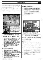
OPERATING THE BOOMS
Boom functions, including the telescopic and slewing
functions, can be operated either from the Platform
Controls or the Chassis Controls.
The Platform controls provide variable speeds for the
boom functions through the use of a Joystick. This is
achieved using an ECU unit which varies the speed
of the motor/pump unit and increases or decreases
the flow of oil to the different functions. This control
unit receives a control signal from the Joystick on the
upper controls, the speed of the motor will increase
as the Joystick is pushed further away from the
neutral (centre) position.
Summary of Contents for AB38
Page 2: ...ii AB38 Work Platform NOTES...
Page 4: ...ii AB38 Work Platform NOTES...
Page 6: ...iv AB38 Work Platform NOTES Foreword...
Page 10: ...Contents Section IV AB38 Work Platform i NOTES...
Page 14: ...Introduction Specifications Section 1 4 AB38 Work Platform NOTES 1 3...
Page 17: ...Machine Preparation Section 2 3 AB38 Work Platform NOTES 2 7...
Page 18: ...Machine Preparation Section 2 4 AB38 Work Platform 2 7 NOTES...
Page 29: ...Operation Section 3 11 AB38 Work Platform NOTES 3 5...
Page 30: ...Operation Section 3 12 AB38 Work Platform NOTES 3 5...
Page 59: ...Maintenance Section 4 29 AB38 Work Platform NOTES 4 21...
Page 60: ...Maintenance Section 4 30 AB38 Work Platform NOTES 4 21...
Page 66: ...Troubleshooting Section 5 6 AB38 Work Platform 5 7 NOTES...
Page 68: ...Schematics Section 6 2 AB38 Work Platform NOTES 6 0...
Page 72: ...Schematics Section 6 6 AB38 Work Platform 6 1 NOTES...
Page 73: ...Electrical Schematic Schematics 6 7 AB38 Work Platform Section 6 1...
Page 74: ...Electrical Schematic Schematics 6 8 AB38 Work Platform Section 6 1 TOP VIEW...
Page 76: ...Schematics Section 6 10 AB38 Work Platform NOTES 6 2...
Page 78: ...Section 6 2 6 12 AB38 Work Platform Schematics NOTES...
Page 81: ...Illustrated Parts Breakdown Section 7 3 AB38 Work Platform 7 2...
Page 83: ...Illustrated Parts Breakdown Section 7 5 AB38 Work Platform 7 2...
Page 85: ...Illustrated Parts Breakdown Section 7 7 AB38 Work Platform 7 2...
Page 87: ...Illustrated Parts Breakdown Section 7 9 AB38 Work Platform 7 2...
Page 89: ...Illustrated Parts Breakdown Section 7 11 AB38 Work Platform 7 2 22...
Page 91: ...Illustrated Parts Breakdown Section 7 13 AB38 Work Platform 7 2...
Page 93: ...Illustrated Parts Breakdown Section 7 15 AB38 Work Platform 7 2...
Page 95: ...Illustrated Parts Breakdown Section 7 17 AB38 Work Platform 7 2...
Page 97: ...Illustrated Parts Breakdown Section 7 19 AB38 Work Platform 7 2...
Page 99: ...Illustrated Parts Breakdown Section 7 21 AB38 Work Platform 7 2...
Page 101: ...Illustrated Parts Breakdown Section 7 23 AB38 Work Platform 7 2...
Page 103: ...Illustrated Parts Breakdown Section 7 25 AB38 Work Platform 7 2...
Page 105: ...Illustrated Parts Breakdown Section 7 27 AB38 Work Platform 7 2...
Page 107: ...Illustrated Parts Breakdown Section 7 29 AB38 Work Platform 7 2...
Page 109: ...Illustrated Parts Breakdown Section 7 31 AB38 Work Platform 7 2...
Page 111: ...Illustrated Parts Breakdown Section 7 33 AB38 Work Platform 7 2...
Page 113: ...Illustrated Parts Breakdown Section 7 35 AB38 Work Platform 7 2...
Page 115: ...Illustrated Parts Breakdown Section 7 37 AB38 Work Platform 7 2...
Page 117: ...Illustrated Parts Breakdown Section 7 39 AB38 Work Platform 7 2...
Page 119: ...Illustrated Parts Breakdown Section 7 41 AB38 Work Platform 7 2 8 9...
Page 121: ...Illustrated Parts Breakdown Section 7 43 AB38 Work Platform 7 2...
Page 123: ...Illustrated Parts Breakdown Section 7 45 AB38 Work Platform 7 2...
Page 125: ...Illustrated Parts Breakdown Section 7 47 AB38 Work Platform 7 2...
Page 127: ...Illustrated Parts Breakdown Section 7 49 AB38 Work Platform 7 2...
Page 131: ...Illustrated Parts Breakdown Section 7 53 AB38 Work Platform 7 2 NOTES...
Page 133: ...Technician s Print AB38 Work Platform Electrical Schematic...

