Operation
Section
3-9
AB38 Work Platform
3.4
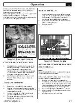
Figure 3-2: Emergency Lowering
Before operating the Emergency
Lowering Valves the surrounding
area should first be cleared of any
potential obstructions. It is also
important that when the valve is
pushed, it is initially done slowly.
This is so that sudden movement
will not occur in the Elevating
Assembly, leading to a potentially
unstable machine.
CONTROL FROM GROUND LEVEL
1.
Chassis Controls are fitted at the base of the
Elevating Assembly. These should be used
when no operator is in the platform (for
maintenance/ service or inspection purposes),
or if the operator has become incapacitated.
For further information see Table 3-1.
2.
Use the appropriate switch to raise or lower
Boom 1, Boom 2, Telescope or rotate as
required.
AFTER USE EACH DAY
1.
Ensure that the platform is fully lowered.
2.
Park the machine on level ground, preferably
undercover, secure against vandals, children or
unauthorised operation.
3.
Turn key switch to
OFF
and remove key to
prevent unauthorised operation.
4.
Recharge batteries in accordance with the
instructions in section 4.2.
Figure 3-3: Manual Rotation
To rotate the Elevating Assembly first apply a 7/8”
socket wrench to the shaft and turn to rotate the
Elevating Assembly. When finished remove the wrench.
MANUAL ROTATION
1.
Ensure booms are lowered as far as possible
using the emergency lowering valves, and that
the Emergency Stop Button is pressed to
prevent any accidental powered operation.
2.
Apply a 7/8” socket wrench to shaft and turn to
rotate elevating assembly.
3.
Remove wrench.
MANUAL TELESCOPIC RETRACTION
(SEE FIGURE 3-4)
NOTE:
Manual Tele Retraction is not required, and hence is
not provided for ANSI machines.
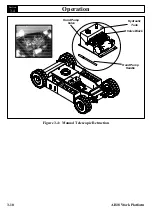
In the event of loss of electrical power the Telescopic
Cylinder can be retracted as follows:
1.
Remove the cover from the chassis body.
2.
The Handpump is attached to the Main Manifold
Block. Remove the Handpump Handle from the
clips on the side of the Chassis and insert into
the Handpump Valve as shown in Figure 3-4.
3.
Operate handpump to retract the tele cylinder.
4.
After use replace the Handpump Handle in the
clips provided.
5.
Reposition the cover on Chassis.
ensure a slow controlled rate of descent at all times.
Descent can be halted at any time by removing
pressure from the red knob.
Repeat the operation if necessary for the upper boom
when cylinder is in reach of the ground.
With both main booms lowered fully it should then be
possible to leave the platform safely.
Apply Socket
Here
Summary of Contents for AB38
Page 2: ...ii AB38 Work Platform NOTES...
Page 4: ...ii AB38 Work Platform NOTES...
Page 6: ...iv AB38 Work Platform NOTES Foreword...
Page 10: ...Contents Section IV AB38 Work Platform i NOTES...
Page 14: ...Introduction Specifications Section 1 4 AB38 Work Platform NOTES 1 3...
Page 17: ...Machine Preparation Section 2 3 AB38 Work Platform NOTES 2 7...
Page 18: ...Machine Preparation Section 2 4 AB38 Work Platform 2 7 NOTES...
Page 29: ...Operation Section 3 11 AB38 Work Platform NOTES 3 5...
Page 30: ...Operation Section 3 12 AB38 Work Platform NOTES 3 5...
Page 59: ...Maintenance Section 4 29 AB38 Work Platform NOTES 4 21...
Page 60: ...Maintenance Section 4 30 AB38 Work Platform NOTES 4 21...
Page 66: ...Troubleshooting Section 5 6 AB38 Work Platform 5 7 NOTES...
Page 68: ...Schematics Section 6 2 AB38 Work Platform NOTES 6 0...
Page 72: ...Schematics Section 6 6 AB38 Work Platform 6 1 NOTES...
Page 73: ...Electrical Schematic Schematics 6 7 AB38 Work Platform Section 6 1...
Page 74: ...Electrical Schematic Schematics 6 8 AB38 Work Platform Section 6 1 TOP VIEW...
Page 76: ...Schematics Section 6 10 AB38 Work Platform NOTES 6 2...
Page 78: ...Section 6 2 6 12 AB38 Work Platform Schematics NOTES...
Page 81: ...Illustrated Parts Breakdown Section 7 3 AB38 Work Platform 7 2...
Page 83: ...Illustrated Parts Breakdown Section 7 5 AB38 Work Platform 7 2...
Page 85: ...Illustrated Parts Breakdown Section 7 7 AB38 Work Platform 7 2...
Page 87: ...Illustrated Parts Breakdown Section 7 9 AB38 Work Platform 7 2...
Page 89: ...Illustrated Parts Breakdown Section 7 11 AB38 Work Platform 7 2 22...
Page 91: ...Illustrated Parts Breakdown Section 7 13 AB38 Work Platform 7 2...
Page 93: ...Illustrated Parts Breakdown Section 7 15 AB38 Work Platform 7 2...
Page 95: ...Illustrated Parts Breakdown Section 7 17 AB38 Work Platform 7 2...
Page 97: ...Illustrated Parts Breakdown Section 7 19 AB38 Work Platform 7 2...
Page 99: ...Illustrated Parts Breakdown Section 7 21 AB38 Work Platform 7 2...
Page 101: ...Illustrated Parts Breakdown Section 7 23 AB38 Work Platform 7 2...
Page 103: ...Illustrated Parts Breakdown Section 7 25 AB38 Work Platform 7 2...
Page 105: ...Illustrated Parts Breakdown Section 7 27 AB38 Work Platform 7 2...
Page 107: ...Illustrated Parts Breakdown Section 7 29 AB38 Work Platform 7 2...
Page 109: ...Illustrated Parts Breakdown Section 7 31 AB38 Work Platform 7 2...
Page 111: ...Illustrated Parts Breakdown Section 7 33 AB38 Work Platform 7 2...
Page 113: ...Illustrated Parts Breakdown Section 7 35 AB38 Work Platform 7 2...
Page 115: ...Illustrated Parts Breakdown Section 7 37 AB38 Work Platform 7 2...
Page 117: ...Illustrated Parts Breakdown Section 7 39 AB38 Work Platform 7 2...
Page 119: ...Illustrated Parts Breakdown Section 7 41 AB38 Work Platform 7 2 8 9...
Page 121: ...Illustrated Parts Breakdown Section 7 43 AB38 Work Platform 7 2...
Page 123: ...Illustrated Parts Breakdown Section 7 45 AB38 Work Platform 7 2...
Page 125: ...Illustrated Parts Breakdown Section 7 47 AB38 Work Platform 7 2...
Page 127: ...Illustrated Parts Breakdown Section 7 49 AB38 Work Platform 7 2...
Page 131: ...Illustrated Parts Breakdown Section 7 53 AB38 Work Platform 7 2 NOTES...
Page 133: ...Technician s Print AB38 Work Platform Electrical Schematic...

