background image

035-19624-001 Rev. A (0104)

Unitary Products Group

5

If a matching cooling coil is used, it may be placed directly on the fur-
nace outlet and sealed to prevent leakage. Follow the coil instructions
for installing the supply plenum. On all installations without a coil, a
removable access panel is recommended in the outlet duct such that
smoke or reflected light would be observable inside the casing to indi-
cate the presence of leaks in the heat exchanger. This access cover
shall be attached in such a manner as to prevent leaks.

RESIDENTIAL AND NON HUD MODULAR HOME 

RETURN PLENUM CONNECTION

Return air may enter the furnace through the side(s) or bottom depend-
ing on the type of application. Return air may not be connected into the
rear panel of the unit. In order to achieve the airflow indicated, it is rec-
ommended those applications over 1800 CFM (57 m³/min) use return
air from two sides, one side and the bottom or bottom only. For single
return application, see data and notes on blower performance data
tables in this manual.

The return duct may be attached to the furnace by S-cleat, bend tabs or
other approved methods. Be sure to seal the duct to the furnace to pre-
vent air leakage.

The furnace must have a return duct system and the return duct system
must terminate outside the area containing the furnace.

BOTTOM RETURN AND ATTIC INSTALLATIONS

Bottom return applications normally pull return air through a base plat-
form or return air plenum. Be sure the return platform structure or return
air plenum is suitable to support the weight of the furnace.

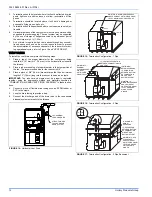
The furnace base is equipped with a rectangular perforated panel that
can be removed by performing the following steps:

1.

Lay the furnace on its back.

2.

Push the panel out from inside the blower compartment.

3.

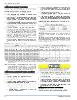
Bend the 3/4” flanges that will be used to attach the return air ple-
num using the scribe marks in the furnace base. Refer to Figure 1
“Bottom Image Return End” and Figure 2 for flange locations.

4.

Be sure to seal the furnace to plenum connections to prevent air
leakage. Refer to Figure 1 for unit and plenum dimensions.

Attic installations must meet all minimum clearances to combustibles
and have floor support with required service accessibility.

IMPORTANT: 

if an external mounted filter rack is being used see the

instructions provided with that accessory for proper hole cut size.

The supply air temperature MUST NEVER  exceed the Maximum
Supply Air Temperature
, specified on the nameplate.
Operating the furnace above the maximum supply air temperature
will cause the heat exchanger to overheat, causing premature heat
exchanger failure. Improper duct sizing, dirty air filters, incorrect
manifold pressure, incorrect gas orifice and a faulty limit switch can
cause the furnace to operate above the maximum supply air tem-
perature. Refer to sections II, III and IX for additional information on
correcting the problem.

 FIGURE 1:  

Dimensions

20

6-3/8

1-1/4

2-3/4

6-1/8

B

A

28-1/2

6-7/8

9-7/8

20-5/8

1-3/4

14-1/2

22-3/4

B

20

A

C

28-1/2

23

3/4

6

1-3/4

4-1/8

3-1/8

8-7/8

45

T’STAT

WIRING

7/8” K.O.

3/4”
FLANGE

TOP IMAGE

SUPPLY END 

BOTTOM IMAGE

RETURN END 

CONDENSATE
DRAIN

OPTIONAL SIDE 
RETURN CUT-OUT 

WITH K.O.
REMOVED

BTUH (kW)

High / Low Fire Inpu

BTUH (kW)

High / Low Fire Output CFM (m

3

/min)

Cabinet

Size

Cabinet Dimension

Air Intake

A

A (cm)

B

B (cm)

C

C (cm)

D

D (cm)

60/39 (17.6/11.4)

55/36 (16.1/11.4)

1200 (33.98)

B

17-1/2

44.4

16-1/4

41.3

13-1/8

33.3

7-1/2

19.1

80/52 (23.4/15.2)

75/48 (21.9/14.1)

1600 (45.31)

C

21

53.3

19-3/4

50.1

16-1/2

41.9

9-1/4

23.5

100/65 (29.3/19.1)

95/60 (27.8/17.6)

2000 (56.63)

C

21

53.3

19-3/4

50.1

16-1/2

41.9

9-1/4

23.5

120/78 (35.1/22.9)

112/72 (32.8/21.1)

2000 (56.63)

D

24-1/2

62.2

23-1/8

58.7

20-1/8

51.1

10-7/8

27.6

GAS PIPE ENTRY
1-1/4 X 2-1/2
(ALL GAS PIPE 

ARE 1/2” NPT)

CONNECTIONS

7/8 JUNCTION
BOX HOLE

LEFT SIDE

FRONT

RIGHT SIDE

FRONT

FRONT

(EITHER SIDE)

 FIGURE 2:  

Furnace Base Rectangular Perforated Panel

There are 8 Tabs to be cut
along this seam around the
rectangular panel.

Removable rectangular
base panel. 

Scribe marks in base panel.
Bend sheet metal down on
these marks to form the 3/4”
flanges.

Summary of Contents for P XU-V/G9V-UP Series

Page 1: ... TABLE OF CONTENTS SAFETY 1 DUCTWORK 3 FILTERS 6 GAS PIPING 6 COMBUSTION AIR AND VENT SYSTEM 9 CONDENSATE DRAIN 16 SAFETY CONTROLS 16 START UP AND ADJUSTMENTS 17 WIRING DIAGRAM 25 LIST OF FIGURES Dimensions 5 Furnace Base Rectangular Perforated Panel 5 Furnace Filter Slot Locations 6 Filter Retainer Placement 6 Side Return Cutout Markings 6 Gas Valve 6 Gas Piping 7 Electrical Wiring 8 Line Wiring ...

Page 2: ...rnace is not approved for installation in trailers or recre ational vehicles Failure to carefully read and follow all instructions in this manual can result in furnace malfunction death personal injury and or property damage Furnaces for installation on combustible flooring shall not be installed directly on carpeting tile or other combustible material other than wood flooring Check the rating pla...

Page 3: ...age to the front when servicing or for inspection or replacement of flue vent connections In all cases accessibility clearances shall take precedence over clear ances for combustible materials where accessibility clearances are greater Installation in a residential garage 13 A gas fired furnace for installation in a residential garage must be installed so the burner s and the ignition source are l...

Page 4: ...l static pressure includes the pressure drop across the return air filter and A coil TABLES 2 AND 3 are to be used as a guide only to help the installer determine if the duct sizes are large enough to obtain the proper air flow CFM through the furnace TABLES 2 and 3 ARE NOT to be used to design ductwork for the building where the furnace is being installed There are several variables associated wi...

Page 5: ...Figure 2 for flange locations 4 Be sure to seal the furnace to plenum connections to prevent air leakage Refer to Figure 1 for unit and plenum dimensions Attic installations must meet all minimum clearances to combustibles and have floor support with required service accessibility IMPORTANT if an external mounted filter rack is being used see the instructions provided with that accessory for prope...

Page 6: ...lter s is provided at another location in the return air system the ductwork may be directly attached to the furnace side panel An accessory filter rack is available for mounting the filter exter nal to the cabinet IMPORTANT Some accessories such as electronic air cleaners and pleated media may require a larger side opening Follow the instruc tions supplied with that accessory for side opening req...

Page 7: ...ernal pressure Never apply a pipe wrench to the body of the gas valve when installing piping A wrench must be placed on the octa gon hub located on the gas inlet side of the valve Placing a wrench to the body of the gas valve will damage the valve causing improper operation and or the valve to leak CHECKING THE GAS PRESSURES 1 The pressure ports on the gas valve are on the inlet and outlet sides o...

Page 8: ...to Figure 8 3 The furnace s control system requires correct polarity of the power supply and a proper ground connection Refer to Figure 9 or FURNACE CONTROL DIAGONSICS for symptoms of reversed power supply polarity IMPORTANT The power connection leads and wiring box may be relo cated to the left side of the furnace Remove the screws and cut wire tie holding excess wiring Reposition on the left sid...

Page 9: ...sions of the local building code and these instructions IMPORTANT The VENT SYSTEM must be installed as specified in these instructions for Residential and Non HUD Modular Homes The sealed combustion air vent system is the only configuration that can be installed in a Non HUD Modular Home FIGURE 10 Field Wiring for Single Stage Thermostat FIGURE 11 Field Wiring for Two Stage Thermostat Set the heat...

Page 10: ...gth the furnace must be converted for high altitude operation Refer to SECTION IV GAS PIPING of these instructions and the proper high altitude application instruction for details NOTE If installing furnace at altitudes between 2000 4500 ft intake and vent pipe length must be reduced by 10 ft If the installation requires the maximum allowable intake and vent pipe length the furnace must be convert...

Page 11: ...listed in vent clearances in these instruc tions 2 Termination should be positioned where vent vapors will not dam age plants or shrubs or air conditioning equipment FIGURE 13 Home Layout L E D B V V V X V B V J X B B B V V F V C B X V I V G H A M K OPERABLE FIXED CLOSED FIXED CLOSED VENT TERMINAL AIR SUPPLY AREA WHERE TERMINAL IS NOT PERMITTED Canadian Installations1 US Installation2 A Clearance ...

Page 12: ...m diameter pipe that has a minimum length of 3 76 mm long into the reducer to serve as a nipple IMPORTANT Tee reducer and nipple must be properly cemented together using the appropriate method and materials specified in COMBUSTION AIR AND VENT PIPING ASSEMBLY in these instruc tions 4 Connect a piece of flexible drain tubing such as EPDM rubber or PVC to the nipple 5 Loop the drain tubing to provid...

Page 13: ...ected to the PVC coupling attached to the burner box and is terminated in the same atmospheric zone as the vent This type of installation is approved on all models 2 AMBIENT COMBUSTION AIR Combustion air is supplied from the area surrounding the furnace through vents or knockouts in the furnace casing The combustion air and the vent pipes are not ter minated in the same atmospheric zone Refer to F...

Page 14: ...res in a fixed louver a grille s or screen shall have no dimension smaller than 0 25 6 4 mm 3 A manually operated damper or manually adjustable louvers are not permitted for use 4 A automatically operated damper or automatically adjustable lou vers shall be interlocked so that the main burner cannot operate unless either the damper or the louver is in the fully open position FIGURE 21 Combustion A...

Page 15: ... OUTDOORS in this instruction or in Section 5 3 Air for Combustion and Ventilation of the National Fuel Gas Code ANSI Z223 1 latest edition This type installation requires two properly sized pipes One brings combustion air from a properly ventilated attic space or crawl space and a second pipe that extends from the furnace vent connection top right of unit to the exterior of the building Refer to ...

Page 16: ...rnace A condensate sump pump MUST be used if required by local codes or if no indoor floor drain is available The condensate sump pump must be approved for use with acidic condensate CONDENSATE DRAIN TRAP AND DRAIN FREEZE PROTECTION Special precautions MUST be made if installing furnace in an area which may drop below freezing This can cause improper operation or damage to the equipment If the fur...

Page 17: ...ow five minutes for any gas to dissipate before continuing with the start up procedure TOOLS AND INFORMATION THAT WILL BE REQUIRED IN ORDER TO PROPERLY PERFORM THE FURNACE STARTUP PROCEDURE 1 Call the local gas supplier to obtain heating value of the natural gas If you cannot obtain the heating valve of the gas from the gas supplier you may use a default value of 1030 BTU SCF 38 8 MJ m 2 You will ...

Page 18: ...ystem during any pressure testing of the system where test pressures are in excess of 1 2 PSI 3 45 kPa CALCULATING THE FURNACE INPUT NATURAL GAS NOTE Front door of burner box must be secured when checking gas input NOTE Burner orifices are sized to provide proper input rate using nat ural gas with a heating value of 1050 BTU Ft3 If the heating value of your gas is significantly different it may be...

Page 19: ...om the gas meter The formula for metric input calculation using a cubic foot gas meter DO NOT ADJUST the manifold pressure regulator if the actual input is equal to or within 8 less than the furnace input specified on the rating plate or if the furnace rise is above the specified rise range on the rating plate If the actual input is significantly higher than the furnace input specified on the rati...

Page 20: ... regulator until pressure shown on manometer matches the pressure specified on the appliance rating plate 6 Replace low adjustment seal screw and tighten securely Cycle the valve several times to verify regulator setting 7 Remove manometer and replace the outlet pressure tap plug Low Outlet Pressure Adjustment 1 Turn off all electrical power to the system at main fuse or circuit breaker 2 Attach a...

Page 21: ...ver if one is not available a 3 speed direct drive motor may be used in the interim Removal of the Variable Speed Blower Assembly and Motor The procedure for removing the direct drive blower assembly is as fol lows 1 Disconnect the electrical supply to the furnace and remove the access doors 2 Remove blower assembly mounting screws and slide the blower assembly out of the slots in the deck If the ...

Page 22: ...nt of the maximum CFM The heating and cooling airflows must be field adjusted to match the HVAC system at installation CFM Timer Board Delay Taps Selection Position A is the factory setting and is used for test purposes The blower will operate at 100 of the cooling airflow for 60 seconds Move the jumper to Position B for a two stage condenser This results in 82 of the cooling airflow with a 45 sec...

Page 23: ...ap ADJ Tap 2030 1090 57 48 30 87 2180 1210 61 73 34 26 A B 1780 945 50 40 26 76 1760 970 49 84 27 47 B B 1890 1000 53 52 28 32 2000 1100 56 63 31 15 A A 1630 850 46 16 24 07 1600 910 45 31 25 77 B A 1685 895 47 71 25 34 1780 990 50 40 28 03 A C 1555 830 44 03 23 50 1540 860 43 61 24 35 C B 1430 785 40 49 22 23 1410 820 39 93 23 22 B C 1310 740 37 10 20 95 1300 770 36 81 21 80 D B 1400 770 39 64 21...

Page 24: ...a to obtain airflow difference 2035 2125 90 CFM 2 55 m3 min Subtract the total system static from 0 50 w c 125 Pa and divide this difference by the difference in ESP values in the table 0 60 w c 150 Pa 0 50 w c 125 Pa to obtain a percentage 0 58 0 50 0 60 0 50 0 8 Multiply percentage by airflow difference to obtain airflow reduction 0 8 X 90 72 Subtract airflow reduction value to airflow 0 50 w c ...

Page 25: ...035 19624 001 Rev A 0104 Unitary Products Group 25 SECTION X WIRING DIAGRAM FIGURE 30 Wiring Diagram ...

Page 26: ...035 19624 001 Rev A 0104 26 Unitary Products Group NOTES ...

Page 27: ...035 19624 001 Rev A 0104 Unitary Products Group 27 ...

Page 28: ...ect to change without notice Printed in U S A 035 19624 001 Rev A 0104 Copyright by York International Corp 2004 All rights reserved Supersedes Nothing Unitary 5005 Norman Product York OK Group Drive 73069 ...

Reviews: