035-19624-001 Rev. A (0104)
Unitary Products Group
21
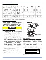
ADJUSTMENT OF TEMPERATURE RISE
The temperature rise, or temperature difference between the return air
and the heated supply air from the furnace, must be within the range
shown on the furnace rating plate and within the application limitations
as shown in Table 7.
After about 20 minutes of operation, determine the furnace temperature
rise. Take readings of both the return air and the heated air in the ducts,
about six feet (1.83 m) from the furnace where they will not be affected
by radiant heat. Increase the blower speed to decrease the temperature
rise; decrease the blower speed to increase the rise.
DIRECT DRIVE MOTORS
Adjustment of Fan-Off Control Settings
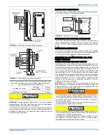
This furnace is equipped with a time-on/time-off heating fan control. The
fan-on is fixed at 30 seconds. The fan-off delay is factory set to 60 sec-
onds; however, it is field-adjustable to 90, 120 or 180 seconds. The fan-
off setting must be long enough to adequately cool the furnace, but not
so long that cold air is blown into the heated space. The continuous fan
speed dip switch (switch 3) on the ignition control has no affect on set-
ting and should be left in the off position, as continuous fan speed is
determined by the variable speed motor program.
Direct Drive Motors (Only Applies to PSC Replacement)
The temperature rise, or temperature difference between the return air
and the heated air from the furnace, must be within the range shown on
the furnace rating plate. Application limitations are shown in Table 7.
After the temperature rise has been determined, the CFM can be calcu-
lated. After about 20 minutes of operation, determine the furnace tem-
perature rise. Take readings of both the return air and the heated air in
the ducts, about six feet from the furnace where they will not be affected
by radiant heat. Increase the blower speed to decrease the temperature
rise; decrease the blower speed to increase the rise. All direct-drive
blowers have multi-speed motors. The blower motor speed taps are
located in the control box in the blower compartment. You may select a
heating speed and a cooling speed. They may be the same speed or a
different speed. To use the same speed tap for heating and cooling, the
heat terminal and cool terminal must be connected using a jumper wire
and connected to the desired motor lead.
Replacement of the Variable Speed Motor with a PSC Direct
Drive Motor
NOTE:
A failed variable speed motor should always be replaced with a
variable speed motor suitable for the furnace model being ser-
viced. However, if one is not available, a 3-speed direct drive
motor may be used in the interim.
Removal of the Variable Speed Blower Assembly and
Motor
The procedure for removing the direct drive blower assembly is as fol-
lows:
1.
Disconnect the electrical supply to the furnace and remove the
access doors.
2.
Remove blower assembly mounting screws and slide the blower
assembly out of the slots in the deck. If the two shipping screws
were not previously removed, also remove and discard these two
screws located on each front corner of the blower assembly.
3.
Loosen the blower wheel set screw and the motor mount bolt, and
slide the variable speed motor out of the blower housing.
4.
To reassemble, reverse the procedure, restore power to the fur-
nace and verify operation.
Installation PSC Motor
1.
Install the PSC direct drive motor into motor mount.
2.
Slide motor in motor mount insuring there is no interference
between moving and stationary parts. Position wire leads down-
ward. Tighten motor mount band screw to 30 in. lbs.
3.
Center the blower wheel in the blower housing and align the shaft
flat with the blower wheel set screw. Tighten setscrew to 30 in. lbs.
4.
Replace blower assembly and fasten with 5 screws
5.
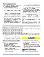
Strap motor capacitor to electric panel. Refer to Table 15, for
proper capacitor selection.
6.
Fasten electric panel to blower housing.
7.
Remove red wire from Circ. input terminal. Plug jumper wire
(attach to motor power harness) on 120-volt line terminal on igni-
tion control and jumper to Circ. Input. Connect brown door switch
wire to jumper.
8.
Connect white main harness lead to Line neutral.
WITH BURNER BOX COVER IN PLACE
WITH BURNER BOX COVER REMOVED
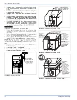
FIGURE 27:
Reading Gas Pressure
6
5
4
3
2
1
0
1
2
3
4
5
6
GAS VALVE
OUTLET
PRESSURE TAP
BURNER BOX PRESSURE
REFERENCE HOSE
BURNER BOX
WITH COVER
TEE
FITTING
U-TUBE
MANOMETER
3.5 IN
WATER COLUMN
GAS PRESSURE
SHOWN
6
5
4
3
2
1
0
1
2
3
4
5
6
GAS VALVE
OUTLET
PRESSURE TAP
BURNER BOX
WITH COVER
REMOVED
BURNER BOX
PRESSURE
REFERENCE HOSE
(NOT USED)
3.5 IN
WATER COLUMN
GAS PRESSURE
SHOWN
U-TUBE
MANOMETER
The temperature rise, or temperature difference between the return
air and the supply (heated) air from the furnace, must be within the
range shown on the furnace rating plate and within the application
limitations shown in Table 7 “ELECTRICAL AND PERFORMANCE
DATA”.
The supply air temperature cannot exceed the “Maximum Supply
Air Temperature” specified in these instructions and on the fur-
nace rating plate. Under NO circumstances can the furnace be
allowed to operate above the Maximum Supply Air Temperature.
Operating the furnace above the Maximum Supply Air Temperature
will cause premature heat exchanger failure, high levels of Carbon
Monoxide, a fire hazard, personal injury, property damage, and/or
death.


