035-19624-001 Rev. A (0104)
22
Unitary Products Group
9.
Connect motor leads to cool, heat lo and heat high per electrical
wire diagram table in the Installation manual.
10. Connect brown capacitor leads from motor to capacitor and cover
terminals with boot supplied.
POWER SUPPLY POLARITY - Ignition Control:
If the power supply
polarity is reversed, the following unit operation will occur. On a call for
heat, the inducer will run, the HSI will glow and the gas valve will ener-
gize and the burners will ignite. The burners will immediately extinguish
and the unit will recycle. This will occur 3 times and then the unit will
lockout. A "7" flash code will be displayed. This code means the flame
could not be established. This occurs because the control cannot sense
flame with the power supply polarity reversed.
VARIABLE SPEED MOTORS
The variable speed motor CFM / Timer Control Board must be config-
ured so the blower will provide a sufficient airflow so that the furnace
operates with in the temperature rise range on the rating plate and
within the application limitations shown in Table 7 in these Instructions.
ADJUSTMENT OF FAN CONTROL SETTINGS
This furnace is equipped with a time-on/time-off heating fan control. The
fan on delay is fixed at 30 seconds. The fan off delay has 4 settings (60,
90, 120 and 180 seconds). The fan off delay is factory set to 120 sec-
onds. The fan-off setting must be long enough to adequately cool the
furnace, but not so long that cold air is blown into the heated space. The
fan-off timing may be adjusted by positioning the jumper on two of the
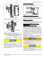
four pins as shown in Figure 28.
Heating Indoor Fan Off Delay
The dip switches are located above the thermostat terminals. Refer to
Figure 28 for the dip switch settings to obtain the desired fan OFF delay.
The blower off delay must be long enough to adequately cool the fur-
nace, but not so long that cold air is blown into the living space.
The blower on delay is fixed at 30 seconds and can not be adjusted.
The continuous fan speed dip switch (switch # 3 on the Integrated Con-
trol) does not function on variable speed models. Dip switch # 3 should
be left in the off position.
Heating and Cooling Airflow
The heating and the cooling airflows are preset at the factory. The heat-
ing airflow is set to the maximum CFM. The cooling airflow is set to pro-
vide 90 percent of the maximum CFM. The heating and cooling airflows
must be field adjusted to match the HVAC system at installation.
CFM / Timer Board: Delay Taps Selection
Position "A" is the factory setting and is used for test purposes. The
blower will operate at 100% of the cooling airflow for 60 seconds.
Move the jumper to Position "B" for a two-stage condenser. This results
in 82% of the cooling airflow with a 45 second off delay.
Move the jumper to position "C" for a system with a TXV or solenoid
valve. This results in 75% of the cooling airflow with a 45 second off
delay.
Move the jumper to position "D" for a system without a TXV or solenoid
valve. This results in 82% of the cooling air flow with a 60 second off
delay.
NOTE:
The blower will have a 15 second coast to stop in all of the
above positions.
Continuous Blower
The Integrated (Ignition) Control does not control the operation of the
blower when it is run in the continuous mode. The CFM / timer Board
controls the blower in the continuous mode through the "G" terminal on
the thermostat. When the thermostat fan-switch is set to the ON posi-
tion a circuit is completed between "R" and "G". This will cause the
blower to operate continuously at 63% of the high cool speed.
If more airflow is desired, you must locate the green wire labeled "G
Cool Speed" which is located in the wire bundle near the Integrated
(Ignition) Control. After the wire has been located, connect it to the "G"
terminal on the Integrated (Ignition) Control. This will cause the blower
to operate at the HIGH COOL speed. Dip switch 3 must be in the OFF
position.
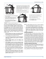
TABLE 15:
Replacement PSC Motor
Low Fire
Heating Input
Low Fire
Heating Output
High Fire
Heating Input
High Fire
Heating Output
Furnace
Airflow
Motor Part
Number
Motor
Horsepower
Capacitor
Part Number
Capacitor
Rating
BTU/H
kW
BTU/H
kW
BTU/H
kW
BTU/H
kW
CFM cm/m
39,000
11.43
36,000
10.55
60,000
17.58
55,000
16.12 1200 33.98 024-23271-000
1/2
024-20045-000
7.5 µf
52,000
15.24
48,000
14.07
80,000
23.45
75,000
21.98 1600 45.31 024-26002-000
3/4
024-20046-000
10.0 µf
65,000
19.05
60,000
17.58
100,000
29.31
95,000
27.84 2000 56.63 024-23288-001
1
024-20446-000
15.0 µf
78,000
22.86
72,000
21.10
120,000
35.17
112,000 32.82 2000 56.63 024-23238-001
1
024-20446-000
15.0 µf
Do not energize more than one motor speed at a time or damage to
the motor will result.
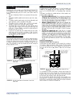
FIGURE 28:
White Rodgers Intergrated Control
INDOOR FAN OFF
DELAY DIP SWITCHES
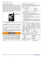
FIGURE 29:
CFM / Timer Board
BLOWER MOTOR
CONNECTIONS
TWO STAGE VARIABLE SPEED THERMOSTAT CONNECTIONS ONLY
HIGH HEA
T
MANUAL TIME
R

