


JOHNSON CONTROLS
8
FORM 145.14-IOM1 (908)
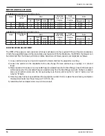
PRE-INSTALLATION INSPECTION OF EQUIPMENT
All units are factory tested to ensure safe operation
and quality assembly. Units are packaged and sealed
on shipping skids and shipped in first class condition.
Torn and broken packaging, scratched or dented pan-
els should be reported to carrier immediately. Internal
inspection of all units should be performed prior to
installation . Remove all access doors and check for
visual defects that can occur during transport. Any prob-
lems found internally should be reported to carrier and
manufacturer immediately. Refrigerant circuit should be
checked to ensure no leaks have occurred during ship-
ment. Install gauge set to high and low pressure ports
to confirm pressure has been maintained and no leaks
have occurred during shipment. Repair any damage
prior to installation to ensure safe operation.
Record any unit damage on the Bill of
Lading and report to carrier and factory
immediately. Shipping and handling
damages are not warranty items.
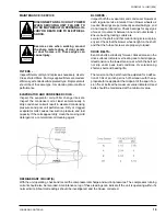
RIGGING
PRIOR TO MOUNTING UNIT, CHECK
INDIVIDUAL UNIT WEIGHTS AND VER-
IFY LIFTING CAPACITY OF LIFTING
EQUIPMENT EXCEEDS WEIGHT OF
UNITS BY SAFE MARGINS. FAILURE TO
DO SO MAY RESULT IN UNIT DAMAGE,
PERSONAL INJURY OR EVEN DEATH.
DETERMINE THE ACTUAL CENTER OF
GRAVITY OF THE UNIT BY PERFORM-
ING A TEST LIFT. LIFTING AN UNBAL
-
ANCED UNIT CAN CAUSE PERSONAL
INJURY OR EVEN DEATH.
INSTALLATION
LOCK ALL ELECTRICAL POWER SUP-
PLY SWITCHES IN THE OFF POSITION
BEFORE INSTALLING THE UNIT. FAIL
-
URE TO DISCONNECT POWER SUPPLY
MAY RESULT IN ELECTRICAL SHOCK
OR EVEN DEATH.
Location - To ensure unit operates at maximum efficien
-
cies, choose a dry indoor area where the temperature
is controlled between 50ºF and 15ºF. Consideration
of surrounding areas should be taken when choosing
a location to install the unit. Common vibration and
sound levels associated with commercial equipment
may be objectionable to people or equipment. Install
thermostats, air supplies and returns so that each unit
will operate only on individual unit control.
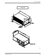
UNIT MOUNTING
The 5 through 10 ton models are shipped as a fully
assembled integral package. Units are not intended for
outdoor installation.
Units may be either hung, or floor mounted. If unit is to be
hung, use all mounting points indicated. The use of 1/2
in. diameter hanger rods is recommended. Ensure the
attachment points of the rods to the building structure are
sufficient to support the unit weight. In order to ensure
efficient condensate drainage, the unit may be pitched
towards the condensate drain outlet end of the unit. A
minimum of 4 in. clearance is required under the unit to
allow for trapping of the evaporator condensate drain.
Floor mounted units should be secured on a solid, level
pad. The use of isolating vibro-pads at several points
under the bottom mounting channels is recommended.
Ensure that provision is made for clearance to install a
trap on the condensate drain outlet.
Summary of Contents for CPH 060
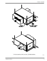
Page 7: ...FORM 145 14 IOM1 908 7 Johnson Controls TYPICAL INSTALLATION LAYOUT CPH060 SHOWN LD13464...
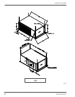
Page 10: ...JOHNSON CONTROLS 10 FORM 145 14 IOM1 908 060 LD13465...
Page 11: ...FORM 145 14 IOM1 908 11 Johnson Controls 096 120 LD13466...
Page 18: ...JOHNSON CONTROLS 18 FORM 145 14 IOM1 908 TYPICAL SCHEMATIC...
Page 20: ...JOHNSON CONTROLS 20 FORM 145 14 IOM1 908 NOTES...
Page 21: ...FORM 145 14 IOM1 908 21 Johnson Controls NOTES...
Page 22: ...JOHNSON CONTROLS 22 FORM 145 14 IOM1 908 NOTES...


