


JOHNSON CONTROLS
16
FORM 145.14-IOM1 (908)
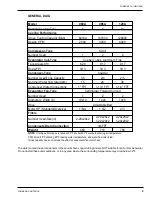
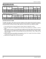
MOTOR AND PULLEY DATA
STANDARD
BLOWER MOTOR AND DRIVE DATA
Model
Drive Range
(RPM)
Motor
Adjustable
Motor Pulley
Fixed
Blower Pulley
Belts
HP
Frame
Size
RPM
Eff.
(%)
Pitch Dia.
(in)
Pitch Dia.
(in)
Designation
Qty
60
946-1419
1
143
1800
82.5
1.9-2.9
3.5
4L-400
1
96
968-1340
1-1/2
145
1800
84.0
2.4-3.4
4.5
4L-440
1
120
1010-1346
2
145
1800
84.0
2.8-3.8
5.0
A43
1
OVERSIZE
BLOWER MOTOR AND DRIVE DATA
Model
Drive Range
(RPM)
Motor
Adjustable
Motor Pulley
Fixed
Blower Pulley
Belts
HP
Frame
Size
RPM
Eff.
(%)
Pitch Dia.
(in)
Pitch Dia.
(in)
Designation
Qty
96
1117-1489
2
145
1800
84.0
2.8-3.8
4.5
A42
1
120
1212-1548
3
145
1800
86.5
3.4-4.4
5.0
A45
1
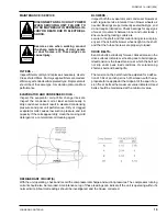
BLOWER SPEED ADJUSTMENT
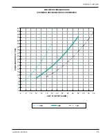
The RPM of the supply air and condenser air blowers will depend on the required CFM, and the static resistances
of both the supply/discharge and the return/intake duct systems. With this information, the RPM for the blowers can
be determined from the blower performance tables. Adjustment of blower speed is accomplished as follows:
1) Loosen belt tension by moving motor towards the blower shaft via the adjustable mounting.
2) Loosen the setscrew in the adjustable motor pulley flange. Remove external key on pulleys 4 in. dia and
larger.
3) Slower speed will increase when moveable flange is adjusted towards the fixed flange (closed). Blower speed
will decrease when the moveable flange is adjusted away from the fixed flange (opened). Pulleys are adjust
-
able only in half-turn increments. Do not open pulley more than five full turns for “4L” and “A” belts, or six full
turns for “B” belts.
4) Once the pulley has been opened/closed the appropriate number of turns, replace the external key and tighten
the adjustment setscrew. Proper torque is 110-130 in.-lbs.
5) Install drive belt and adjust motor mount to tension belt.
Summary of Contents for CPH 060
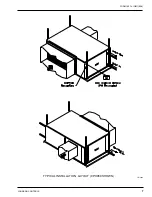
Page 7: ...FORM 145 14 IOM1 908 7 Johnson Controls TYPICAL INSTALLATION LAYOUT CPH060 SHOWN LD13464...
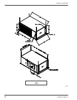
Page 10: ...JOHNSON CONTROLS 10 FORM 145 14 IOM1 908 060 LD13465...
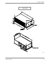
Page 11: ...FORM 145 14 IOM1 908 11 Johnson Controls 096 120 LD13466...
Page 18: ...JOHNSON CONTROLS 18 FORM 145 14 IOM1 908 TYPICAL SCHEMATIC...
Page 20: ...JOHNSON CONTROLS 20 FORM 145 14 IOM1 908 NOTES...
Page 21: ...FORM 145 14 IOM1 908 21 Johnson Controls NOTES...
Page 22: ...JOHNSON CONTROLS 22 FORM 145 14 IOM1 908 NOTES...


