Unitary products group CPH 060 Installation & Operation Instructions Download Page 3

FORM 145.14-IOM1 (908)

3

JOHNSON CONTROLS

CHANGEABILITY OF THIS DOCUMENT

In complying with Johnson Controls policy for continu-

ous product improvement, the information contained 

in this document is subject to change without notice. 

While Johnson Controls makes no commitment to up-

date or provide current information automatically to the 

manual owner, that information, if applicable, can be 

obtained by contacting the nearest Johnson Controls 

service office.

It is the responsibility of operating/service personnel as 

to the applicability of these documents to the equipment 

in question. If there is any question in the mind of oper-

ating/service personnel as to the applicability of these 

documents, then, prior to working on the equipment, they 

should verify with the owner whether the equipment has 

been modified and if current literature is available.

Work on this equipment should only be done by properly trained personnel who are qualified to 

work on this type of equipment.  Failure to comply with this requirement could expose the worker, 

the equipment and the building and its inhabitants to the risk of injury or property damage.

The instructions are written assuming the individual who will perform this work is a fully trained 

HVAC & R journeyman or equivalent, certified in refrigerant handling and recovery techniques, and 

knowledgeable with regard to electrical lock out/tag out procedures.  The individual performing 

this work should be aware of and comply with all national, state and local safety and environ

-

mental regulations while carrying out this work.  Before attempting to work on any equipment, 

the individual should be thoroughly familiar with the equipment by reading and understanding 

the associated service literature applicable to the equipment.  If you do not have this literature, 

you may obtain it by contacting a Johnson Controls Service Office.

Should there be any question concerning any aspect of the tasks outlined in this instruction, 

please consult a Johnson Controls Service Office prior to attempting the work.  Please be aware 

that this information may be time sensitive and that Johnson Controls  reserves the right to revise 

this information at any time.  Be certain you are working with the latest information.

Summary of Contents for CPH 060

Page 1: ...l CPH Horizontal Water Cooled Air Conditioning Unit Supersedes 145 14 IOM1 708 Form 145 14 IOM1 908 MODEL CPH 060 096 120 HORIZONTAL WATER COOLED AIR CONDITIONING UNITS INSTALLATION OPERATION INSTRUCT...

Page 2: ...It is essential that prior to performing any task on this equipment this individual shall have read and understood this document and any referenced materials This individual shall also be familiar wit...

Page 3: ...uld expose the worker the equipment and the building and its inhabitants to the risk of injury or property damage The instructions are written assuming the individual who will perform this work is a f...

Page 4: ...ite Selection 8 General Data 9 Dimensional Data 10 Water Piping 12 Water Pressure Drop 13 Supply Return Air Ductwork 14 Electrical 14 Wiring 15 Fan Performance Data 15 Motor and Drive Data 16 RPM Adju...

Page 5: ...60 3 6 265 60 1 8 380 415 3 60 Control Options E Std Electro Mechanical Controls K Remote Management Relay Kit M LCCS Control System F Future Options ID Motor 1 Standard Air Side Coil 2 High Static 3...

Page 6: ...ls mounted on durable rubber isolators to reduce vibra tion and noise while operating Each refrigerant circuit is equipped with high pressure and low pressure switches All models are equipped with an...

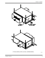
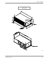
Page 7: ...FORM 145 14 IOM1 908 7 Johnson Controls TYPICAL INSTALLATION LAYOUT CPH060 SHOWN LD13464...

Page 8: ...ONAL INJURY OR EVEN DEATH INSTALLATION LOCK ALL ELECTRICAL POWER SUP PLY SWITCHES IN THE OFF POSITION BEFORE INSTALLING THE UNIT FAIL URE TO DISCONNECT POWER SUPPLY MAY RESULT IN ELECTRICAL SHOCK OR E...

Page 9: ...9 17 9 17 Rows FPI 3 13 3 13 3 13 Condenser Type Coaxial Number Used Tons Capacity 1 5 2 4 2 5 Nominal Water flow rate gpm 15 24 30 Condenser Water Connections 1 FPT 1 1 4 FPT 1 1 4 FPT Evaporator Fan...

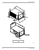
Page 10: ...JOHNSON CONTROLS 10 FORM 145 14 IOM1 908 060 LD13465...

Page 11: ...FORM 145 14 IOM1 908 11 Johnson Controls 096 120 LD13466...

Page 12: ...each internal condenser water circuit The water regulating valve needs to be adjusted to maintain a leaving water temperature between 90 F and 100 F If using a refrigerant discharge pressure gauge adj...

Page 13: ...nson Controls WATERSIDE PRESSURE DROP STANDARD UNIT MANIFOLDED CONDENSERS 0 2 4 6 8 10 12 14 16 18 20 22 24 26 28 30 32 34 36 38 40 6 8 10 12 14 16 18 20 22 24 26 28 30 32 34 UNIT FLOW RATE GPM PRESSU...

Page 14: ...t specifications by checking unit data plate All electrical components are accessible through an independent electrical panel located on the right hand side of the unit condenser compressor section Th...

Page 15: ...PM BHP RPM BHP 1800 846 0 41 936 0 48 1024 0 56 1107 0 64 1195 0 74 1259 0 82 1325 0 90 1400 0 99 060A 2000 917 0 54 999 0 62 1079 0 71 1157 0 79 1233 0 89 1305 0 98 2200 994 0 70 1069 0 79 1142 0 88...

Page 16: ...istances of both the supply discharge and the return intake duct systems With this information the RPM for the blowers can be determined from the blower performance tables Adjustment of blower speed i...

Page 17: ...alled and operated Verification of proper direction is made by observing that suction pressure drops and discharge pressure rises when the compressor is energized Reverse rota tion also results in an...

Page 18: ...JOHNSON CONTROLS 18 FORM 145 14 IOM1 908 TYPICAL SCHEMATIC...

Page 19: ...l Clean blower wheels as needed Bearings are permanently sealed ball type and do not require lubrication Check bearings for any signs of wear movement between inner and outer races Ensure bearing lock...

Page 20: ...JOHNSON CONTROLS 20 FORM 145 14 IOM1 908 NOTES...

Page 21: ...FORM 145 14 IOM1 908 21 Johnson Controls NOTES...

Page 22: ...JOHNSON CONTROLS 22 FORM 145 14 IOM1 908 NOTES...

Page 23: ...n replacing the compressor is not covered by this Warranty LABOR AND COST NOT COVERED This Warranty provides only replacement parts or credits and does not provide for or cover any labor shipping hand...

Page 24: ...without notice Printed in U S A Copyright 2008 by Unitary Products Group All rights reserved Form 145 14 IOM1 908 Supersedes 145 14 IOM1 708 York PA 17405 P O Box 1592 York PA 17405 Engineered System...

Reviews: