


JOHNSON CONTROLS
14
FORM 145.14-IOM1 (908)
DUCTWORK
When installing ductwork, adhere to local Codes and
sensible practice. Minimize duct runs and avoid abrupt
changes in direction where possible. Allow ample access
space for servicing of the coils and changing of filters.
Perform regular maintenance on ducts to increase unit
life, maintain efficient operation, and reduce accumu
-
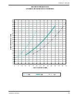
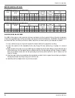
lation of explosive dust. Refer to blower performance
charts, and engineer duct runs and accessory pres-
sure drop so as not to exceed maximum external static
values.
Canvas or other types of flexible collars are recom
-
mended for connecting the air ducts to the unit. The
supply air duct collar can be connected directly to the
blower outlet flanges. Return air may be ducted to the
unit, or drawn directly from the return air space. If a
ducted return is desired, duct connection flanges may
be secured directly to the filter frame flanges. The filter
frame on 5, 8 and 10 ton models has duct attachment
flanges incorporated into the filter rack.
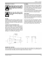
ELECTRICAL WIRING
Follow local electrical codes when making electrical con-
nections. Units are completely factory wired for normal
supply voltages (ie.208-230, 460, 575/3phase/60hz)
Confirm unit specifications by checking unit data plate.
All electrical components are accessible through an
independent electrical panel located on the right hand
side of the unit (condenser/compressor section). The
electrical control boxes are located behind outer ac-
cess panels. The compressor section electrical cover
is provided with wiring diagrams on the inside, which
must be opened to be read.
Provide individual power disconnects for each unit.
Install a secure ground to the bonding lug located in
the electrical control panel. If canvas flexible joints are
used on ductwork, install a ground wire to the ductwork
as well.
DISCONNECT AND LOCK OUT POWER
WHEN SERVICING UNIT. UNIT MAY
START AUTOMATICALLY IF POWER
IS NOT DISCONNECTED. FAILURE TO
DO SO MAY RESULT IN PERSONAL IN-
JURY OR DEATH DUE TO ELECTRICAL
SHOCK.
All wiring must comply with applicable
local and national codes (NEC). Type and
location of disconnect switches must
comply with all applicable codes.
Unit requires installer to provide a 24volt thermostat
with appropriate heating and cooling stages as needed.
For low voltage wiring, 18 gauge wire may be used for
up to 50 feet lengths. Low voltage runs up to 125 feet
require 16 gauge wire.
All models are designed for single zone cooling applica-
tions, utilizing space or return air thermostatic controls.
A low voltage terminal block is provided for hook-up of
conventional or programmable thermostats.
Summary of Contents for CPH 060
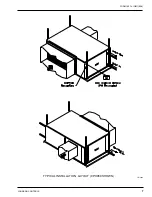
Page 7: ...FORM 145 14 IOM1 908 7 Johnson Controls TYPICAL INSTALLATION LAYOUT CPH060 SHOWN LD13464...
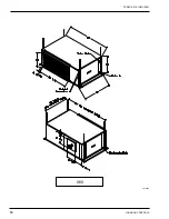
Page 10: ...JOHNSON CONTROLS 10 FORM 145 14 IOM1 908 060 LD13465...
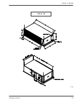
Page 11: ...FORM 145 14 IOM1 908 11 Johnson Controls 096 120 LD13466...
Page 18: ...JOHNSON CONTROLS 18 FORM 145 14 IOM1 908 TYPICAL SCHEMATIC...
Page 20: ...JOHNSON CONTROLS 20 FORM 145 14 IOM1 908 NOTES...
Page 21: ...FORM 145 14 IOM1 908 21 Johnson Controls NOTES...
Page 22: ...JOHNSON CONTROLS 22 FORM 145 14 IOM1 908 NOTES...


