


FORM 145.14-IOM1 (908)
17
JOHNSON CONTROLS
START-UP AND OPERATION
Prior to starting unit for the first time,
turn the thermostat system switch to
OFF - or raise the cooling setpoint to the
highest temperature to prevent the unit
from starting, then close the electrical
disconnect switch.
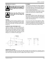
Start unit and check rotation of fans and compressors.
Scroll compressors will only compress in one rotational
direction. Three phase compressors will rotate in either
direction depending upon phasing of the power. Since
there is a 50-50 chance of connecting power in such a
way as to cause rotation in the reverse direction, it is
important to ensure proper rotation direction is achieved
when the system is installed and operated.
Verification of proper direction is made by observing
that suction pressure drops and discharge pressure
rises when the compressor is energized. Reverse rota-
tion also results in an elevated sound level as well as
substantially reduced current draw.
There is no negative impact on durability caused by
operating three phase Scroll compressors in the re-
versed direction for a short period of time (under one
hour). However, after several minutes of operation the
compressors internal protector will trip.
If opposite rotation is needed, disconnect and reverse
any two leads of the three phase supply. Reconnect
power and observe for correct rotation.
Observe unit operation and check for unusual noise or
vibration.
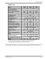
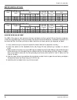
Ref. Charge
5 TON
8 TON
10 TON
No. of Circuits
1
2
2
Per Circuit (lb)
4.625
4.188
5.125
High
Low
Cut Out (PSIG)
400
25
Cut In (PSIG)
275
60
PRESSURE SWITCH SETTINGS - ALL MODELS
Summary of Contents for CPH 060
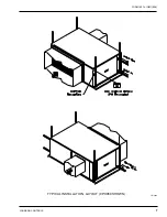
Page 7: ...FORM 145 14 IOM1 908 7 Johnson Controls TYPICAL INSTALLATION LAYOUT CPH060 SHOWN LD13464...
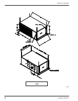
Page 10: ...JOHNSON CONTROLS 10 FORM 145 14 IOM1 908 060 LD13465...
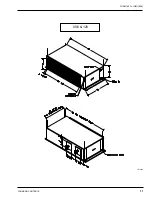
Page 11: ...FORM 145 14 IOM1 908 11 Johnson Controls 096 120 LD13466...
Page 18: ...JOHNSON CONTROLS 18 FORM 145 14 IOM1 908 TYPICAL SCHEMATIC...
Page 20: ...JOHNSON CONTROLS 20 FORM 145 14 IOM1 908 NOTES...
Page 21: ...FORM 145 14 IOM1 908 21 Johnson Controls NOTES...
Page 22: ...JOHNSON CONTROLS 22 FORM 145 14 IOM1 908 NOTES...


