


JOHNSON CONTROLS
6
FORM 145.14-IOM1 (908)
GENERAL INFORMATION
Our units are designed to accommodate the ever-
changing installation requirements of today’s market.
All models 5 - 10 tons are shipped as factory-charged
unitized packages. Low profile design allows the unit to
be installed on the floor or suspended from the ceiling.
CPH models feature a ‘straight-through’ airflow configu
-
ration. Units are completely factory wired and piped.
These units are designed to allow easy passage through
doors, hallways and elevators. All unit components are
securely mounted inside the heavy gauge “Galvalume”
steel cabinet. All units are lined with 1/2” thick - 2 lb
density acoustical insulation to ensure the quietest op-
eration. All models are provided with medium- efficiency
2” thick throwaway filters.
The 5 ton model has a single refrigerant circuit. The 8
and 10 ton models are dual compressor units with two in-
dependent compressor/ condenser circuits. Evaporator
coils are of copper tube and rippled aluminum plate fin
construction. The high-efficiency tube-in-tube condens
-
ers feature a convoluted inner tube design for optimum
performance. Standard models feature a copper inner
tube surrounded by a steel outer tube, and carry a 400
psig working pressure rating. Multiple refrigerant circuit
models feature internally manifolded condensers (single
water in, water out connection).
High efficiency Scroll compressors are used in all mod
-
els, mounted on durable rubber isolators to reduce vibra-
tion and noise while operating. Each refrigerant circuit is
equipped with high pressure and low pressure switches.
All models are equipped with an adjustable thermal ex-
pansion valve (with external equalizer), one valve per
circuit. Each refrigerant circuit is also equipped with a
liquid line filter drier, sight glass/moisture indicator, and
service access ports. An electrically re-setable lock-out
relay will shut off the compressor in the event of pressure
switch trip during operation. Control circuit operates on
24V, and features an oversized transformer. Optional
anti-short circuit timers can be field/factory installed.
Installation time is minimized with all models. When plan-
ning an installation consider power supply, thermostat,
condensate drain line, duct run, and service clearances.
A remote thermostat device is field supplied and installed
to control the unit operation.
Service access doors are equipped with lifting handles,
and are located on both sides of the unit to allow easy
servicing of all components.
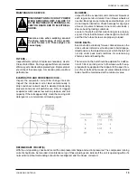
All units are equipped with centrifugal blowers combined
with variable pitch adjustable pulleys. Forward curved
double width, double inlet blowers are used for evapo-
rator air movement. All models employ a draw-through
air flow arrangement. Large evaporator coil face areas
reduce noise levels, air pressure drops, and minimize
potential condensate blow-off. All blower wheels are
galvanized steel, with solid steel shafts supported in
permanently lubricated ball bearings. V-belts drive all
models and blower RPM can be adjusted through the
motor sheave.
Summary of Contents for CPH 060
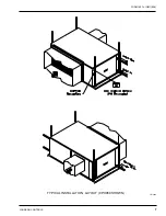
Page 7: ...FORM 145 14 IOM1 908 7 Johnson Controls TYPICAL INSTALLATION LAYOUT CPH060 SHOWN LD13464...
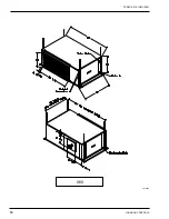
Page 10: ...JOHNSON CONTROLS 10 FORM 145 14 IOM1 908 060 LD13465...
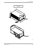
Page 11: ...FORM 145 14 IOM1 908 11 Johnson Controls 096 120 LD13466...
Page 18: ...JOHNSON CONTROLS 18 FORM 145 14 IOM1 908 TYPICAL SCHEMATIC...
Page 20: ...JOHNSON CONTROLS 20 FORM 145 14 IOM1 908 NOTES...
Page 21: ...FORM 145 14 IOM1 908 21 Johnson Controls NOTES...
Page 22: ...JOHNSON CONTROLS 22 FORM 145 14 IOM1 908 NOTES...


