


FORM 145.14-IOM1 (908)
23
JOHNSON CONTROLS
LIMITED WARRANTY
Johnson Controls warrants this product to be free from defects in workmanship or material for a period of one year from date of original
installation or 18 months from date of shipment, whichever comes first
Johnson Controls obligation under this Warranty is LIMITED to repairing or replacing at our sole option, at our factory, any part thereof
which shall be returned to our factory, transportation charges prepaid and which on examination proves to have been thus defective
under normal domestic use not exceeding the fuel rating. The defective part should be returned through a qualified servicing dealer.
Upon warranty determination, the replacement part will be shipped freight collect and assumes the unexpired portion of this Limited
Warranty.
When a defective part can be repaired or replaced, Johnson Controls shall not be obligated to repair the entire unit or any part thereof
other than the defective part.
This warranty applies only to the original homeowner, and is subject to the terms and conditions hereof.
COMPRESSOR – FIVE YEAR LIMITED WARRANTY
In addition to the One Year Limited Warranty, Johnson Controls warrants the compressor to be free from defects in workmanship or
material for a period of five (5) years from the date of original installation. If a compressor fails during this five year period, a new com
-
pressor will be supplied. The customer will be responsible for freight costs from our factory for delivery of the replacement compres-
sor and also for the return of the defective compressor which may be required under the terms of the Warranty. Labor and any other
expense involved in replacing the compressor is not covered by this Warranty.
LABOR AND COST NOT COVERED
This Warranty provides only replacement parts or credits, and does not provide for or cover any labor, shipping, handling or other costs
for service travel, servicing, removing, or installing any parts.
EXCLUSIONS
This Warranty shall be void if:
1. The unit is not installed by a licensed or otherwise qualified or contractor and in compliance with the Installation Manual, applicable
installation and good trade practices.
2. The defect or damage is caused by accident, abuse, negligence of any person or company, misuse, riot, flood, fire or Acts of
God.
3. The unit is not operated and regularly serviced and maintained as called for in the Users’ Manual.
4. Damages are caused by operating the unit in a commercial or corrosive atmosphere containing any damaging or dangerous
chemicals.
5. The unit is modified or services in a manner not in accordance with the Installation Manual and Users’ Manual.
6. Components, replacement parts, or other accessories not compatible with the unit or not approved by Johnson Controls have
been used with or attached to the unit.
7. The defect or damage is not caused by Skymark, or it arises from circumstances beyond the control of Johnson Controls.
8. The unit is installed outside the United States or Canada, or has been removed from the place where it was originally installed.
THIS WARRANTY IS IN LIEU OF ALL OTHER WARRANTIES, OBLIGATIONS OR LIABILITIES, EXPRESSED OR IMPLIED BY
EMPLOYEES OR REPRESENTATIVES OF JOHNSON CONTROLS. ALL STATUTORY, EXPRESSED OR IMPLIED WARRANTIES,
INCLUDING THE IMPLIED WARRANTY OF MERCHANTABILITY AND FITNESS FOR A PARTICULAR PURPOSE ARE HEREBY
NEGATED AND EXCLUDED. ANY CLAIMS FOR INCIDENTAL AND CONSEQUENTIAL DAMAGES, OR ANY OTHER DAMAGES
OR EXPENSES BEYOND THE TERMS OF THIS LIMITED WARRANTY ARE HEREBY EXPRESSLY NEGATED AND EXCLUDED.
Summary of Contents for CPH 060
Page 7: ...FORM 145 14 IOM1 908 7 Johnson Controls TYPICAL INSTALLATION LAYOUT CPH060 SHOWN LD13464...
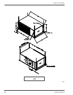
Page 10: ...JOHNSON CONTROLS 10 FORM 145 14 IOM1 908 060 LD13465...
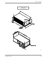
Page 11: ...FORM 145 14 IOM1 908 11 Johnson Controls 096 120 LD13466...
Page 18: ...JOHNSON CONTROLS 18 FORM 145 14 IOM1 908 TYPICAL SCHEMATIC...
Page 20: ...JOHNSON CONTROLS 20 FORM 145 14 IOM1 908 NOTES...
Page 21: ...FORM 145 14 IOM1 908 21 Johnson Controls NOTES...
Page 22: ...JOHNSON CONTROLS 22 FORM 145 14 IOM1 908 NOTES...


