C.I.B. UNIGAS
- M039144CD
32
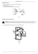
Replacing the ignition electrode
To replace the ignition electrode, proceed as follows:
1
remove the burner cover
2
disconnect the electrode cable
3
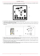
remove the combustion head (see par. “Removing the combustion head”);
4
loosen the screw that fastens the ignition electrode to the burner ignitor;
5
remove the electrode and replace it referring to the measures shown on Fig. 25.
Cleaning and replacing the detection photoresistor
To clean/replace the detection photoresistor, proceed as follows:
1
Disconnect the system from the electrical power supply.
2
Shut off the fuel supply
3
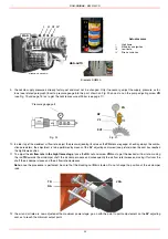
remove the photoresistor from its slot ;
4
if necessary, replace the photocell with a new one;
5
replace the photoresistor into its slot.
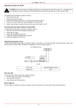
Checking the detection current
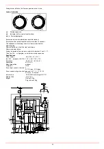
To measure the detection signal follow the diagram in figure. If the signal is not in the advised range, verify the electrical contacts, the
cleaning of the combustion head, the position of the photoresistor and if necessary replace it.
Fig. 26
Seasonal stop
To stop the burner in the seasonal stop, proceed as follows:
1
turn the burner’s main switch to 0 (Off position)
2
disconnect the power mains
3
close the fuel cock of the supply line
Burner disposal
In case of disposal, follow the instructions according to the laws in force in your country about the “Disposal of materials”.
ATTENTION:
avoid
the ignition and detection electrodes to contact metallic parts (blast tube, head, etc.), otherwise the boi-
ler’s operation would be compromised. Check the electrodes position after any intervention on the combustion head.
Control box
Minumum detection signal
Siemens LAL
8µA
MC TERMINAL BLOCK
34
35
SCALE
µA DC
Summary of Contents for RG1025
Page 2: ......
Page 18: ...C I B UNIGAS M039144CD 18 BERGONZO NOZZLES Fig 15 ...
Page 19: ...C I B UNIGAS M039144CD 19 Fig 16 ...
Page 20: ...C I B UNIGAS M039144CD 20 Fig 17 ...
Page 21: ...C I B UNIGAS M039144CD 21 Fig 18 ...
Page 38: ......
Page 39: ......


