C.I.B. UNIGAS
- M039144CD
13
Hydraulic diagrams for light oil supplying circuits
NOTE:
in plants where gravity or ring feed systems are provided, install an automatic interception device (see n. 4 - Fig. 5)
Pump operating principle
The pumps that are used can be installed both into single-pipe and double-pipe systems.
Single-pipe system:
a single pipe drives the oil from the tank to the pump’s inlet. Then, from the pump, the pressurised oil is driven to
the nozzle: a part comes out from the nozzle while the othe part goes back to the pump. In this system, the by-pass pulg, if provided,
must be removed and the optional return port, on the pump’s body, must be sealed by steel plug and washer.
Double-pipe system:
as for the single pipe system, a pipe that connects the tank to the pump’s inlet is used besides another pipe that
connects the pum’s return port to the tank, as well. The excess of oil goes back to the tank: this installation can be considered self-ble-
eding. If provided, the inside by-pass plug must be installed to avoid air and fuel passing through the pump.
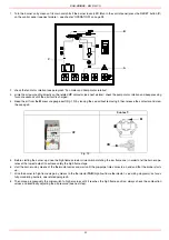
Burners come out from the factory provided for double-stage systems. They can be suited for single-pipe system (recommended in the
case of gravity feed) as decribed before.To change from a 1-pipe system to a 2-pipe-system, insert the by-pass plug
G
(as for ccw-rota-
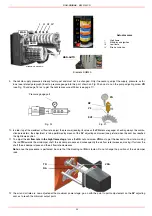
Fig. 6 - Gravity circuit
Fig. 7 - Ring circuit
Fig. 8 - Suction circuit
Key
1
Manual valve
2
Light oil filter
3
Light oil feeding pump
4
One way valve
5
Flexible hoses
6
Relief valve
Summary of Contents for RG1025
Page 2: ......
Page 18: ...C I B UNIGAS M039144CD 18 BERGONZO NOZZLES Fig 15 ...
Page 19: ...C I B UNIGAS M039144CD 19 Fig 16 ...
Page 20: ...C I B UNIGAS M039144CD 20 Fig 17 ...
Page 21: ...C I B UNIGAS M039144CD 21 Fig 18 ...
Page 38: ......
Page 39: ......


