


C.I.B. UNIGAS
- M039144CD
9
MOUNTING AND CONNECTIONS
ATTENTION: READ CAREFULLY THE “WARNINGS2 CHATPER AT THE BEGINNIG OF THIS MANUAL.
To get rid of the burner’s packing and in the event of scrapping of the latter, follow the procedures laid down by current laws on disposal
of materials.
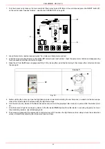
Handling the burner
The burner is provided with eyebolts, for handling operations.
The burner is designed to work positioned according to the picture below. For different
installations, please contact the Technical Department.
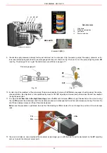
Matching the burner to the boiler
The burners described in this manual have been tested with combustion chambers that comply with EN676 regulation and whose
dimensions are described in the diagram . In case the burner must be coupled with boilers with a combustion chamber smaller in dia-
meter or shorter than those described in the diagram, please contact the supplier, to verify that a correct matching is possible, with
respect of the application involved. To correctly match the burner to the boiler verify the necessary input and the pressure in combu-
stion chamber are included in the burner performance curve; otherwise the choice of the burner must be revised consulting the burner
manufacturer. To choose the blast tube lenght follow the instructions of the boiler manufacturer. In absence of these consider the fol-
lowing:
Cast-iron boilers, three pass flue boilers (with the first pass in the rear part): the blast tube must protrude no more than 100 mm into
the combustion chamber.
Pressurised boilers with flame reversal: in this case the blast tube must penetrate at least 50 - 100 mm into combustion chamber in
respect to the tube bundle plate.
The length of the blast tubes does not always allow this requirement to be met, and thus it may be necessary to use a suitably-sized
Packing
The burners are despatched in wooden cages whose dimensions are:
2270 x 1720 x 1360mm (L x P x H)
Packing cases of this kind are affected by humidity and are not suitable for stacking.
In each packing case, you will find:
burner;
flexible hoses;
light oil filter;
ceramic fibre plait to be inserted between the burner and the boiler;
envelope containing this manual.
ATTENTION! the lfting and moving operations must be carried out by
specialised and trained personnel. If these operations are not carried out
perfectly, there is the residual risk of the burner to overturn and fall
down.
As for moving the burner, use means suited for the weight to sustain
(see paragraph “Technical specifications”).
H
P
L
Eyebolts
SIDE UP
SIDE
DOWN
Summary of Contents for RG1025
Page 2: ......
Page 18: ...C I B UNIGAS M039144CD 18 BERGONZO NOZZLES Fig 15 ...
Page 19: ...C I B UNIGAS M039144CD 19 Fig 16 ...
Page 20: ...C I B UNIGAS M039144CD 20 Fig 17 ...
Page 21: ...C I B UNIGAS M039144CD 21 Fig 18 ...
Page 38: ......
Page 39: ......


