Unigas RG1025 Manual Of Installation, Use And Maintenance Download Page 35

42

SIEMENS LAL.. CONTROL BOX FOR OIL BURNERS 

Use

Control and supervision of oil atomization burners

For burners of medium to high capacity

For intermittent operation (at least one controlled shutdown every 24
hours)

Universally applicable for multistage or modulating burners

Housing and plug-in base

Made of impact-proof and heat-resistance black plastic

Lockout reset button with viewing window; located behind it:

Lockout warning lamp

Lockout indicator coupled to the spindle of the sequence switch and
visible in the transparent lockout reset button

uses easy-to-remember symbols to indicate the type of fault and the
point in time lockout occurred

Base and plug-in section of the LAL... are designed such that only burner
controls of the LAL... family can be plugged in.

24 connection terminals

Auxiliary terminals «31» and «32»

3 earth terminals terminating in a lug for earthing the burner

3 neutral conductor terminals prewired to terminal 2

14 knockout holes for cable entry by means of cable glands

8 at the side

6 in the bottom of the base

6 lateral threaded knockout holes for cable entry glands Pg11 or M20

Operation

Flame detector and flame simulation test are made automatically during
burner off times and the prepurge time «t1». If loss of flame occurs during
operation, the burner control will initiate lockout. If automatic repetition of
the startup sequence is required, the clearly marked wire link on the plug-
in section of the LAL... must be cut away.

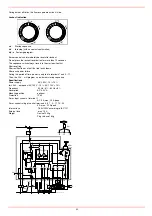
Pre-conditions for burner startup

Burner control is not in the lockout position

Sequence switch is in its start position (with LAL2 voltage is present at
terminals 11 and 12.

Air damper is closed; end switch «z» for the CLOSED position must
feed power from terminal 11 to terminal8.

Contact of the limit thermostat or pressure switch «W» and the con-
tacts of any other switching devices in the control loop between termi-
nals 4 and 5 must be closed  e.g. a control contact for the oil
preheater’s temperature

Normally closed contact of the air pressure switch must be closed.
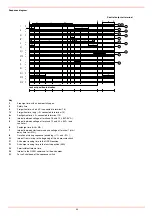
Startup sequence

Start command by «R»:
 «R» closes the start control loop between terminals 4 and 5

The sequence switch starts to run

Only prepurging, fan motor at terminal 6 receives power

Pre- and postpurging, fan motor or flue gas fan at terminal 7 receives
power on completion of «t7»

On completion of «t16», the control command for opening the air dam-
per is delivered via terminal 9

Terminal 8 receives no power during the positioning time

The sequence switch continues to run only after the air damper has
fully closed.

t1

Prepurge time with air damper fully open:

The correct functioning of the flame supervision circuit is checked
during «t1»

The burner control will initiate lockout if correct functioning is not ensu-
red.

With LAL2:
Shortly after the beginning of «t1», the air pressure switch must change
over from terminal 13 to terminal 14 otherwise, the burner control will ini-
tiate lockout  start of the air pressure check.
t3

Short preignition time:

«Z» must be connected to terminal 16, release of fuel via terminal 18.

t3’

Long preignition time: «Z» connected to terminal 15.

t3n

Postignition time:

- «Z» must be connected to terminal 15
- With short preignition, «Z» remains on until «TSA» has elapsed  connec-
tion to terminal 16.
t4

Interval «BV1 – BV2» or «BV1 - LR»: On completion of «t4», vol-

tage is present at terminal 19. The voltage is required to power «BV2»
connected to auxiliary switch «v» in the actuator.
t5

Interval: On completion of «t5», terminal 20 receives power. At the

same time, control outputs 9 to 11 and input 8 are galvanically separated
from the LAL...’s control section.
LAL... is now protected against reverse voltages from the load control
circuit. With the release of «LR» at terminal 20, the startup sequence of
the LAL... ends. After a few idle steps (steps with no contact position
changes), the sequence switch switches itself off.
B

Operating position of the burner

B-C

Burner operation: during burner operation, «LR» drives the air

damper to the nominal load or low-fire position, depending on heat
demand; the release of the nominal load takes place via auxiliary switch
«v» in the actuator and in the event of loss of flame during operation, the
LAL... will initiate lockout. For automatic start repetition, the clearly mar-
ked wire link «B» on the plugin section of the LAL... must be cut away.
C

Controlled shutdown: in the case of controlled shutdown, «BV...»

will immediately be closed. At the same time, the sequence switch is star-
ted to program «t6»
C-D Sequence switch travels to start position «A»
t6

Postpurge time: fan «M2» connected to terminal 7. Shortly after the

start of «t6», terminal 10 receives power and the air damper is driven to
the MIN position. Full closing of the air damper starts only shortly before
«t6» has elapsed initiated by the control signal at terminal 11. During the
following burner off time, terminal 11 is live.
t13

Permissible afterburn time: during «t13», the flame signal input

may still receive a flame signal.
D-A

End of control program:  start position

As soon as the sequence switch has reached the start position – having
thereby switched itself off – the flame detector and flame simulation test
will start again.
During burner off times, the flame supervision circuit is live.

Lockout and indication of the stop position

Whenever a fault occurs, the sequence switch stops and with it the
lockout indicator. The symbol appearing above the reading mark indicates
the type of fault:

No start. One of the contacts is not closed (also refer to «Precondi-

tions for burner startup»):

Extraneous light:
Lockout during or after completion of the control program
Examples: nonextinguished flame, leaking fuel valves faulty flame super-
vision circuit.

Interruption of startup. No OPEN signal at terminal 8 from the chan-

geover end switch «a». Terminals 6, 7 and 15 are live until fault has

been corrected

P

Lockout

.  

No air pressure indication at the beginning of the air pres-

sure check. Air pressure failure after the air pressure check.

Defect in the flame supervision circuit.
Interruption of the startup sequence. No positioning signal at termi-

nal 8 from the auxiliary switch «m» for the low-fire position. Terminals

6, 7 and 15 are live until fault has been corrected.
1

Lockout. No flame signal at the end of the safety time.

|

Flame signa has been lost during operation.

A

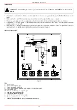
Consenso all’avviamento (ad esempio tramite il termostato o il 
pressostato R dell’impianto

B

Operating position of the burner

B-C

Burner operation: during burner operation, «LR» drives the air

damper to the nominal load or low-fire position, depending on heat
demand; the release of the nominal load takes place via auxiliary switch
«v» in the actuator and in the event of loss of flame during operation, the
LAL... will initiate lockout. For automatic start repetition, the clearly mar-
ked wire link «B» on the plugin section of the LAL... must be cut away.
C

Controlled shutdown: in the case of controlled shutdown, «BV...»

will immediately be closed. At the same time, the sequence switch is star-
ted to program «t6»
C-D Sequence switch travels to start position «A».

APPENDIX

Summary of Contents for RG1025

Page 1: ...MANUAL OF INSTALLATION USE MAINTENANCE RG1025 RG1030 RG1040 M039144CD Rel 3 2 09 2010 BURNERS BRUCIATORI BRULERS BRENNER QUEMADORES ГОРЕЛКИ Light oil burners ...

Page 2: ......

Page 3: ...s electricity gas oil or other fuel Observe caution with hot burner components These are usually near to the flame and the fuel pre heating system they become hot during the unit operation and will remain hot for some time after the burner has stopped When the decision is made to discontinue the use of the burner the user shall have qualified personnel carry out the following operations a Remove t...

Page 4: ...c or explosive mixtures DIRECTIVES AND STANDARDS Gas burners European directives Directive 2009 142 EC Gas Appliances Directive 2006 95 EC on low voltage Directive 2004 108 EC on electromagnetic compatibility Harmonised standards UNI EN 676 Gas Burners CEI EN 60335 1 Household and similar electrical appliances Safety Part 1 General requirements EN 50165 Electrical equipment of non electric applian...

Page 5: ...l and air to perform clean and efficient combustion is activated by atomisation of oil into very small particles This process is achieved making pressurised oil passing through the nozzle The pump 11 main function is to transfer oil from the tank to the nozzle in the desired quantity and pressure To adjust this pressure pumps are provided with a pressure regulator except for some models for which ...

Page 6: ...he intersection point A is inside the performance curve Fig 2 Data are referred to standard conditions atmospheric pressure at 1013mbar ambient temperature at 15 C Burner model identification Burners are identified by burner type and model Burner model identification is described as follows Type RG1025 Model G PR S A 1 2 3 4 5 6 1 BURNER TYPE RG1025 RG1030 RG1040 2 FUEL G Light oil 3 OPERATION Ava...

Page 7: ... combustion head to its MIN position During the first ignition the combustion head is set in order to find a compromise between the burner output and the generator specifications that is why the minimum output may be different from the Per formance curve minimum BURNERS RG1025 RG1030 RG1040 Output min max kW 2550 8700 2550 10600 2550 13000 Light oil rate min max kg h 215 734 215 894 215 1096 Fuel ...

Page 8: ... template A S A L AA AB AC AD AE B S B L BB C CC D E F G H K L M N O P RR SS UU W Y Z RG1025 1896 2090 377 1452 651 25 585 350 544 641 1546 680 1502 680 822 370 410 660 816 M16 651 460 460 265 80 142 1146 379 330 RG1030 1914 2108 377 1452 651 25 585 350 544 657 1564 680 1502 680 822 422 472 660 816 M16 651 460 460 265 80 142 1146 379 330 RG1040 1961 2155 377 1452 651 25 585 386 580 657 1575 680 15...

Page 9: ...must be revised consulting the burner manufacturer To choose the blast tube lenght follow the instructions of the boiler manufacturer In absence of these consider the fol lowing Cast iron boilers three pass flue boilers with the first pass in the rear part the blast tube must protrude no more than 100 mm into the combustion chamber Pressurised boilers with flame reversal in this case the blast tub...

Page 10: ...all the burner into the boiler 6 fix the burner to the stud bolts by means of the fixing nuts according to the picture below 7 After fitting the burner to the boiler ensure that the gap between the blast tube and the refractory lining is sealed with appropriate insulating material ceramic fibre cord or refractory cement Pilot gas train Fig 4 Key 1 Burner 2 Gas valves 3 Minimum gas pressure switch ...

Page 11: ...y network must be carried out Once the gas train in installed execute the electrical connections for all its items gas valves group pressure switch ATTENTION once the gas train is mounted according to the diagram on Fig 4 the gas proving test mus be performed according to the procedure set by the laws in force connection to the gas supply network ...

Page 12: ...re executing the electrical connections pay attention to turn the plant s switch to OFF and be sure that the burner s main switch is in 0 position OFF too Read carefully the chapter WARNINGS and the Electrical connections section WARNING The burner is provided with an electrical bridge between terminals 6 and 7 when connecting the high low flame thermostat remove this bridge before connecting the ...

Page 13: ...e sealed by steel plug and washer Double pipe system as for the single pipe system a pipe that connects the tank to the pump s inlet is used besides another pipe that connects the pum s return port to the tank as well The excess of oil goes back to the tank this installation can be considered self ble eding If provided the inside by pass plug must be installed to avoid air and fuel passing through...

Page 14: ...to bleed To avoid damages inject some lubrication oil into the vacuum inlet Care must be taken when installing the pump not to force the pump shaft along its axis or laterally to avoid excessive wear on the joint noise and overloading the gears Pipes should not contain air pockets Rapid attachment joint should therefore be avoided and threaded or mechanical seal jun ctions preferred Junction threa...

Page 15: ... two flexible hoses on the pump being careful to avoid exchanging the inlet and return lines see the arrows marked on the pump that show the inlet and the return see prevoius paragraph Pressure adjustment Remove cap nut 1 and the gasket 2 unscrew the lock nut 4 To increase pressure twist adjusting screw 3 clockwise To decrease the pressure twist screw counterclockwise Tight the lock nut 4 refit th...

Page 16: ...back nozzle is feeded at constant pressure while the return line pressure is adjusted by means of the pressure governor controlled by an actuator coupled to an adjusting cam The fuel amount to be burnt is adjusted by means of the burner actuator according to the adjustments set see prevoius paragraph Fig 10 Stand by Fig 11 Prepurge Fig 12 Low flame Fig 13 High flame Key 1 Oil pump 2 Oil solenoid v...

Page 17: ...FLAME RETURN PRESSURE bar NOZZLE 25 18 21 recommended 7 recommended Tab 1 Fig 14 Atomisation angle according to the return pressure _________ Flow rate FLOW RATE kg h DIMENSIONS Min Max 40 13 40 50 16 50 60 20 60 70 23 70 80 26 80 90 30 90 100 33 100 115 38 115 130 43 130 145 48 145 160 53 160 180 59 180 200 66 200 225 74 225 250 82 250 275 91 275 300 99 300 330 109 330 360 119 360 400 132 400 450...

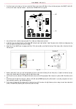
Page 18: ...C I B UNIGAS M039144CD 18 BERGONZO NOZZLES Fig 15 ...

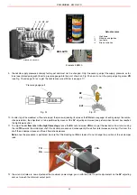
Page 19: ...C I B UNIGAS M039144CD 19 Fig 16 ...

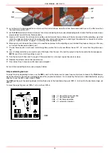
Page 20: ...C I B UNIGAS M039144CD 20 Fig 17 ...

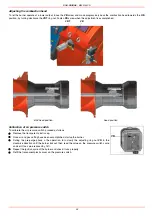
Page 21: ...C I B UNIGAS M039144CD 21 Fig 18 ...

Page 22: ...to the points between maximum and minimum set the foil shape of the adju sting cam The adjusting cam sets the air fuel ratio in those points regulating the opening closing of the fuel governor Set now the low flame output acting on the low flame microswitch of the actuator in order to avoid the low flame output increasing too much or that the flues temperature gets too low to cause condensation in...

Page 23: ...then release the contactor and srew the cap again Fig 19 5 Before starting the burner up drive the high flame actuator microswitch matching the low flame one in order to let the burner ope rates at the lowest output to achieve safely the high flame stage 6 start the burner up by means of the thermostat series and wait until the pre purge time comes to an end and that the bruner starts up 7 drive t...

Page 24: ...low rate in the high flame stage loose the RA nut and screw VRA as to get the desired air flow rate moving the rod TR towards the air damper shaft the air damper opens and consequently the air flow rate increases moving it far from the shaft the air damper closes and the air flow rate decreases Note once the procedure is perfomed be sure that the blocking nut RA is fasten Do not change the positio...

Page 25: ...st be set 20 30 more than the ignition posi tion 18 cam IV stroke limitation cam must be set a little higher than the cam III to limit the output in the first seconds the flame appears NOTE cam IV must shift according to cam III 19 Turn the burner off then start it up again If the adjustment is not correct repeat the previous steps 20 Replace the actuator and control panel covers 21 Now adjust the...

Page 26: ... the air pressure switch proceed as follows Remove the transparent plastic cap Once air and gas setting have been accomplished startup the burner During the pre purge phase o the operation turn slowly the adjusting ring nut VR in the clockwise direction until the burner lockout then read the value on the pressure switch scale and set it to a value reduced by 15 Repeat the ignition cycle of the bur...

Page 27: ...T AND SAFE FUNCTIONING OF THE BURNER THEREFORE ANY OPERATION OF THE APPLIANCE MUST BE PREVENTED WHICH DEPARTS FROM THE INSTALLATION OPERATIONS OR WHICH HAPPENS AFTER TOTAL OR PARTIAL TAMPERING WITH THESE E G DISCONNECTION EVEN PARTIAL OF THE ELECTRICAL LEADS OPENING THE GENERATOR DOOR DISMANTLING OF PART OF THE BURNER NEVER OPEN OR DISMANTLE ANY COMPONENT OF THE MACHINE OPERATE ONLY THE MAIN SWITC...

Page 28: ...nds later the servocontrol switches to high flame lights A and B on or remains in low flame light B on and light A off according to the needs of the plant Burner control panel Fig 22 Key A Burner switch B Burner lockout signaling light C Control box release pushbutton E CMF Automatic Manual operation switch only for fully modulating models EVG Fuel solenoid valve EVS Solenoid valve EVG operation s...

Page 29: ...tion photoresistor adjustment and if necessary replacement page 32 Remove and clean the fuel nozzle Important cleaning must be performed using solvent not metal tools At the end of maintenance operations after the burner reassembly light the flame and check its shape replacing the nozzle whenever a questio nable flame shape appears Whenever the burner is used intensely we recommend preventively re...

Page 30: ...Remove the top cover C 2 remove the photoresistor from its seat 3 unscrew the revolving connectors E in Fig 23 on the fuel pipes use 2 spanners to avoid loosening the connections attached to the distributor block 4 loosen the screw VRT to free the threaded rod AR then screw out the 2 screws V holding the washer R and the screw VRT in posi tion 5 remove the whole assembly as shown in Fig 23 6 Clean...

Page 31: ...bove in the reversed order Fig 24 Electrode and nozzle position setting To guarantee a good ignition the masures below in mm must be observed Fig 25 Fig 25 ATTENTION avoid the ignition and detection electrodes to contact metallic parts blast tube head etc otherwise the boi ler s operation would be compromised Check the electrodes position after any intervention on the combustion head A 8 mm B 3 mm...

Page 32: ...lot Checking the detection current To measure the detection signal follow the diagram in figure If the signal is not in the advised range verify the electrical contacts the cleaning of the combustion head the position of the photoresistor and if necessary replace it Fig 26 Seasonal stop To stop the burner in the seasonal stop proceed as follows 1 turn the burner s main switch to 0 Off position 2 d...

Page 33: ...EATS THE CYCLE DURING OPE RATION MAIN SWITCH OPEN LINE FUSE INTERVENTION MAX PRESSURE SWITCH FAULT FAN THERMAL CUTOUT INTERVENTION AUXILIARY RELAIS FUSES INTERVENTION CONTROL BOX FAULT SERVOCONTROL FAULT SMOKEY FLAME IGNITION TRANSFORMER FAULT IGNITION ELECTRODE DIRTY OR BADLY POSITIONED DIRTY NOZZLE FUEL SOLENOID VALVE DEFECTIVE PHOTORESISTOR DIRTY OR DEFECTIVE HI LO FLAME THERMOSTAT DEFECTIVE WR...

Page 34: ...BRAHMA EG R12 2190502 2190502 2190502 FLEXIBLE HOSES L 1500 1 M x 1 F 2340004 2340004 2340004 FLEXIBLE HOSES L 800 1 2 M x 1 2 F 2340027 2340027 FLEXIBLE HOSES L 600 3 8 2340049 FLEXIBLE HOSES L 385 3 8 2340088 2340088 FLEXIBLE HOSES L 485 3 8 2340089 2340089 2340089 GAS FLEXIBLE HOSES 1 2 M 234FX07 234FX07 234FX07 FLEXIBLE HOSES L 347 1 2 F x 1 2 F 234FX24 ADJUSTING CAM FOIL 2440013 2440054 24400...

Page 35: ... actuator t5 Interval On completion of t5 terminal 20 receives power At the same time control outputs 9 to 11 and input 8 are galvanically separated from the LAL s control section LAL is now protected against reverse voltages from the load control circuit With the release of LR at terminal 20 the startup sequence of the LAL ends After a few idle steps steps with no contact position changes the seq...

Page 36: ...tartup sequence Specifications Power supply AC 230 V 15 10 for LAL2 on request AC 100 V 15 AC 110 V 10 Frequency 50 Hz 6 60 Hz 6 Absorption AC 3 5 VA Mounting position optional Protection IP 40 Perm input current at terminal 1 AC 5 A max 20 A peak Perm current rating of control terminals 3 6 7 9 11 15 20 4 A max 20 A peak Internal fuse T6 3H250V according to IEC 127 External fuse max 10 A Weight D...

Page 37: ...at terminal 7 start delay time for M2 t8 Duration of startup sequence excluding t11 and t12 t10 Interval from startup to the beginning of the air pressure check t11 Air damper running time to the OPEN position t12 Air damper running time to the low fire position MIN t13 Permissible afterburn time t16 Interval to the OPEN command for the air damper t20 For self shutdown of the sequence switch A t11...

Page 38: ......

Page 39: ......

Page 40: ...d and data subject to change Errors and omissions excepted C I B UNIGAS S p A Via L Galvani 9 35011 Campodarsego PD ITALY Tel 39 049 9200944 Fax 39 049 9200945 9201269 web site www cibunigas it e mail cibunigas cibunigas it ...

Reviews: