SECTION 7
41
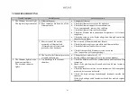
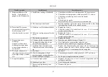
7. TROUBLESHOOTING
Trouble symptom
Possible cause
Corrective action
1. The filament does not light.
The high voltage is normal.
A. Filament burnout
a. Change the filament.
B. Poor contact or broken wire of the
filament cable.
a. Check the filaments set-screws for tightness.
b. Check the filament support for contamination.
If it is contaminated, remove it by rubbing.
c. Check the filament terminal for breakage.
d. Check the filament cable connection for tightness. If it is loose,
retighten it.
e. Check the screws on the high voltage feed-through outside the
chamber for tightness.
C. Short-circuit of the emitter
assembly or filament lead.
(Filament control circuit and
protective fuse burnout.)
a. Short-circuit of filament and beam former.
b. Check if metal particles are caught in the filament holder.
c. Check the filament lead for short-circuit.
d. Check if the specified filament setscrews are used.
(Too long screws will cause shorting.)
D. The fuse for the filament protective
circuit has blown out.
a. Change the fuse and refer to 1 (C).
b. Failure of EB power supply (See its instruction manual.)
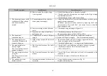
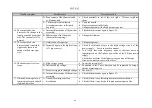
2. The filament lights, but no
beam current flows.
The overload indicator
lights.
A. Arc discharge in the vacuum
chamber.
a. Check the filament cables for contamination and insulation film
formation.
b. Check if the gap between the anode plate and beam former is
large enough.
c. Check the insulator surface for contamination. If discharge has
occurred, its trace can be located.
d. Check the high voltage feed-through terminals outside the
chamber.
If the high voltage cable insulation sheath has melted, replace
the cable.
Summary of Contents for EGL-206M
Page 2: ...EB0007 03e...
Page 3: ...EB0007 03e...
Page 10: ......
Page 13: ...SECTION 1 3 Fig 1 1 Dimensional Drawing for EGL 206M EGL 406M...
Page 24: ...SECTION 3 14 Fig 3 1 Installation of two or more electron beam guns...
Page 26: ...SECTION 3 16 Fig 3 3 Typical water cooling piping arrangement...
Page 27: ...SECTION 3 17 Fig 3 4 Wiring arrangement in vacuum chamber...
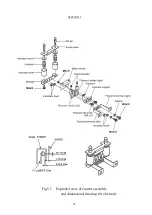
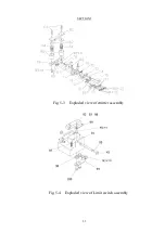
Page 38: ...SECTION 5 28 Fig 5 1 Exploded view of emitter assembly and dimensional drawing for electrode...
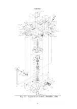
Page 42: ...SECTION 5 32 Fig 5 2 Exploded view of EGL 206M EGL 406M...


